
Substrate processing apparatus

a processing apparatus and substrate technology, applied in the direction of instruments, cleaning using liquids, photosensitive materials, etc., can solve the problem of difficulty in further speeding up the transportation of substrates, and achieve the effect of improving the processing ra

Active Publication Date: 2014-01-21
SCREEN SEMICON SOLUTIONS CO LTD
View PDF19 Cites 9 Cited by
  • Summary
  • Abstract
  • Description
  • Claims
  • Application Information

AI Technical Summary

Benefits of technology

[0008]An object of the present invention is to provide a substrate processing apparatus in which throughput can be improved.

Problems solved by technology

However, it is difficult to further speed up transportation of the substrates, because the transport speed of the substrates by the transport mechanism has been set sufficiently high.

Method used


Image

  • Substrate processing apparatus
  • Substrate processing apparatus
  • Substrate processing apparatus

Examples


second modification

[0242](10-1) Second Modification

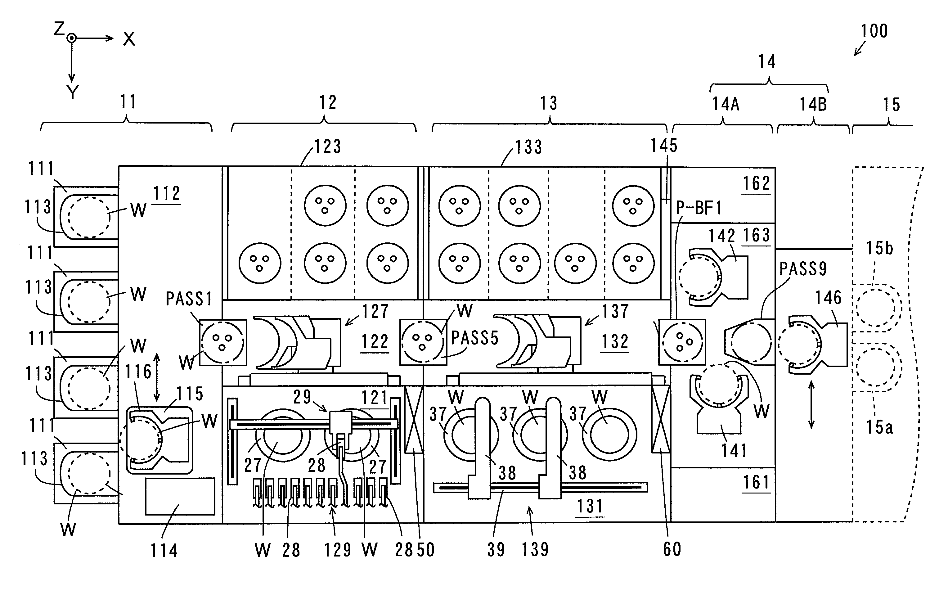
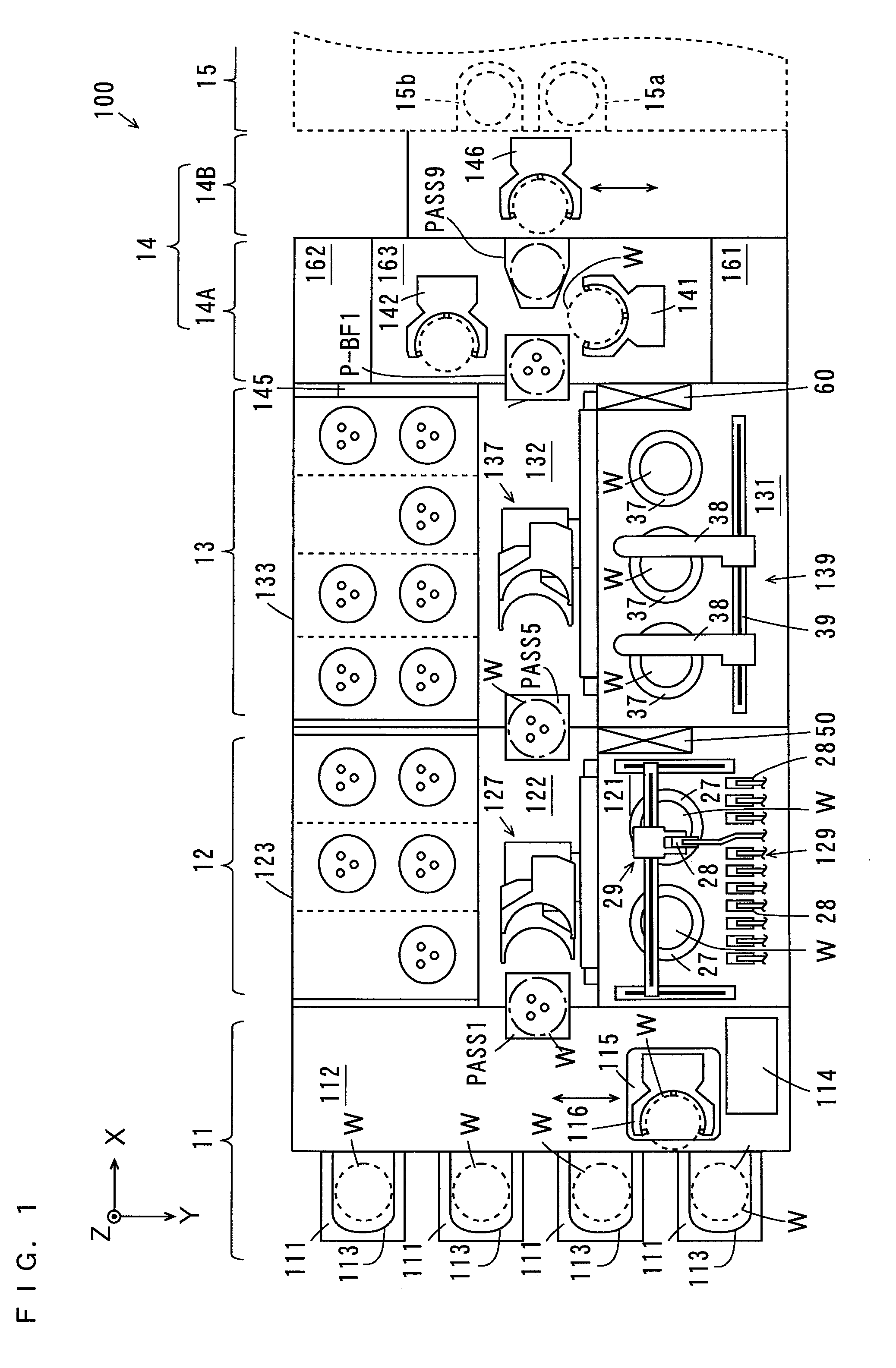
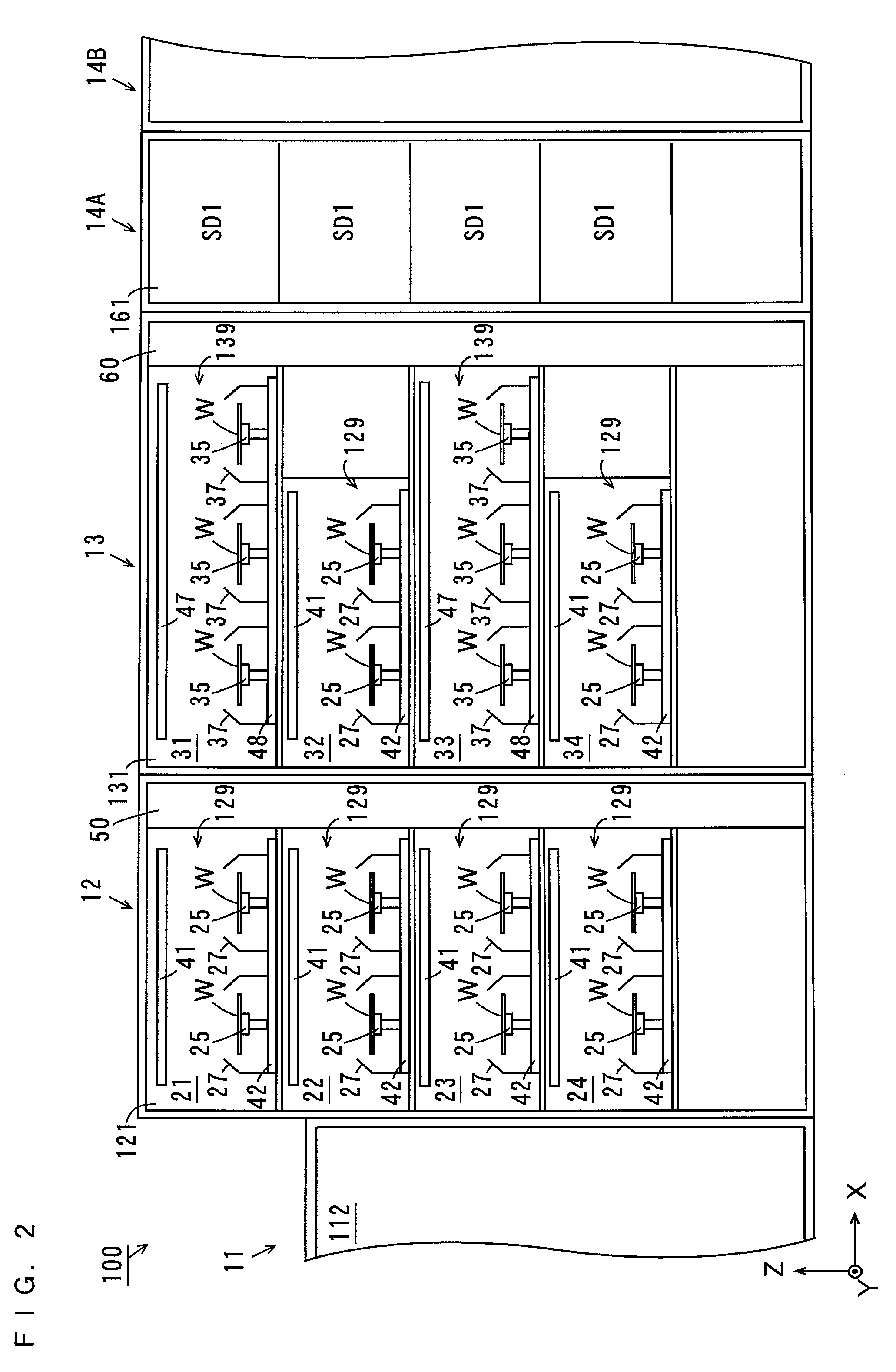
[0243]A second modification is described while referring to differences from the foregoing embodiment. FIG. 16 is a diagram showing the internal configuration of the cleaning / drying processing block 14A in the second modification. Note that FIG. 16 is a diagram of the cleaning / drying processing block 14A that is seen from the +X direction.

[0244]As shown in FIG. 16, the plurality of (five in this example) cleaning / drying processing units SD2 are provided in each of the cleaning / drying processing sections 161, 162 in the second modification.

[0245]One example of the transport paths of the substrates W in the cleaning / drying processing block 14A of FIG. 16 is described mainly referring to FIGS. 5 and 16.

[0246]The substrates W after the edge exposure placed in the placement / buffer sections P-BF1, P-BF2 by the transport mechanisms 137, 138 (FIG. 5) are transported to the placement / cooling sections P-CP (FIG. 5) by the transport mechanisms 141, 142 (FIG. 16)...


PUM


Abstract

An interface block is constituted by a cleaning / drying processing block and a carry-in / carry-out block. The cleaning / drying processing block includes cleaning / drying processing sections and a transport section. The transport section is provided with a transport mechanism. The carry-in / carry-out block is provided with a transport mechanism. The transport mechanism carries substrates in and out of an exposure device.

Description

BACKGROUND OF THE INVENTION[0001]1. Field of the Invention[0002]The present invention relates to a substrate processing apparatus that subjects substrates to various types of processing.[0003]2. Description of the Background Art[0004]Substrate processing apparatuses are used to subject various types of substrates such as semiconductor substrates, substrates for liquid crystal displays, plasma displays, optical disks, magnetic disks, magneto-optical disks, and photomasks, and other substrates to various types of processing.[0005]For example, a substrate processing apparatus described in JP 2003-324139 A includes a plurality of processing blocks. Each processing block is provided with a plurality of thermal processing sections, a plurality of chemical solution processing sections and a transport mechanism. In each processing block, substrates are transported to the thermal processing sections and the chemical solution processing sections by the transport mechanism. Then, the substrate...

Claims


Application Information

Patent Timeline
Patent Type & Authority Patents(United States)
IPC IPC(8): B08B3/00
CPCH01L21/67178H01L21/67225H01L21/67748H01L21/67742H01L21/67303G03F7/20Y10S134/902
Inventor HAMADA, TETSUYATAGUCHI, TAKASHI
Owner SCREEN SEMICON SOLUTIONS CO LTD
Learn More