Implantable medical assembly and methods

a technology of medical assembly and medical components, applied in the field of implantable medical assembly and methods, can solve the problems of my medical method, assembly and system being susceptible to modification, and achieve the effects of reducing resistance within the valve system, preventing the collapse of the chamber, and increasing the fluid velocity

Active Publication Date: 2014-01-21
AHMED A MATEEN
View PDF158 Cites 42 Cited by
  • Summary
  • Abstract
  • Description
  • Claims
  • Application Information

AI Technical Summary

Benefits of technology

[0013]One embodiment is an ophthalmological device for treating glaucoma. In this embodiment the medical device is the Ahmed glaucoma valve. This glaucoma valve comprises a non-obstructive, self-regulating pressure control system having an inlet tube coming from the anterior chamber of the eye into the anterior side of this valve system. The posterior end of the inlet tube enters a pre-tensioned valve membrane sandwiched between the top and bottom plates of this valve, forming a trapezoidal venturi cavity, having a larger inlet opening and narrowing down to smaller opening, helping to increase the velocity of fluid within this cavity, which helps to evacuate the eye fluid, thereby reducing resistance within the valve system.
[0014]This glaucoma valve is encased within the cover, which encloses essentially the entire glaucoma valve. In one embodiment the cover has a porous portion with a unique variable pore size formed from spherical beads or by another method. A portion of the cover's chamber is enlarged at an entrance or proximal end where the valve body is placed. The variable porous portion of the chamber tapers down from the proximal end towards a distal end. Thus the chamber forms an envelope with constant tapering sections between top and bottom porous walls. The chamber has sidewalls that are rigid so they support the top and bottom walls, preventing collapse of the chamber. These sidewalls may or may not be porous. The tapering of the envelope or chamber is thus configured into...

Problems solved by technology

My medical method, assembly and system are, however, susceptible to modifications and alte...

Method used


Image

  • Implantable medical assembly and methods
  • Implantable medical assembly and methods
  • Implantable medical assembly and methods

Examples


Embodiment Construction

.” The claims that follow define my medical assembly, cover, and implantation methods, distinguishing them from the prior art.

DESCRIPTION OF THE DRAWING

[0018]Some embodiments of my method, assembly and system are discussed in detail in connection with the accompanying drawing, which is for illustrative purposes only. This drawing includes the following figures (FIGS.), with like numerals indicating like parts:

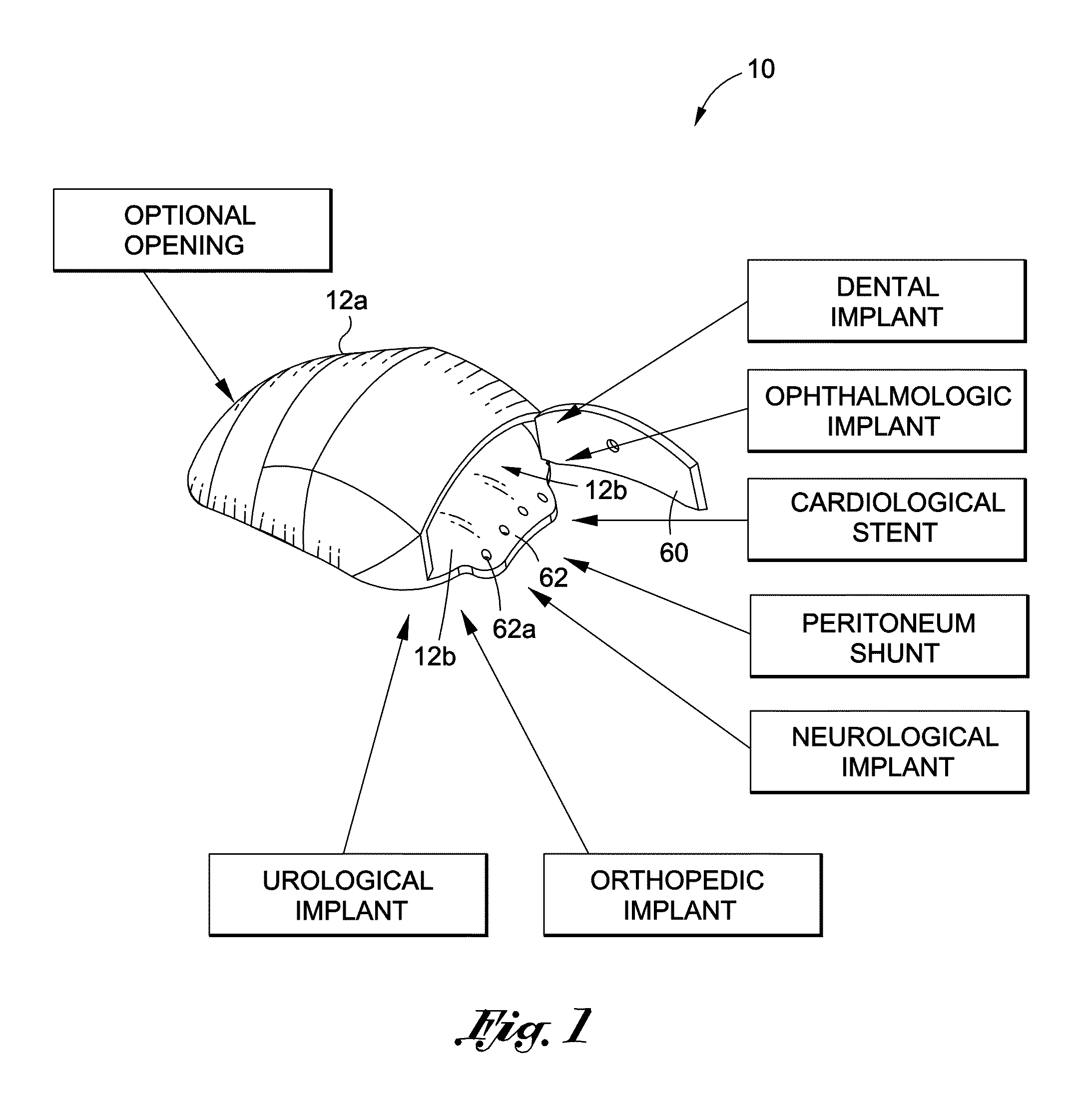
[0019]FIG. 1 is a schematic diagram depicting my implantable medical assembly.

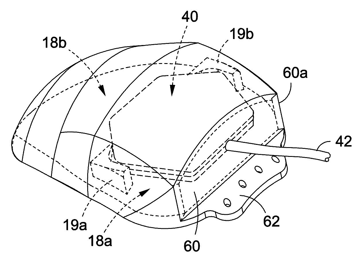
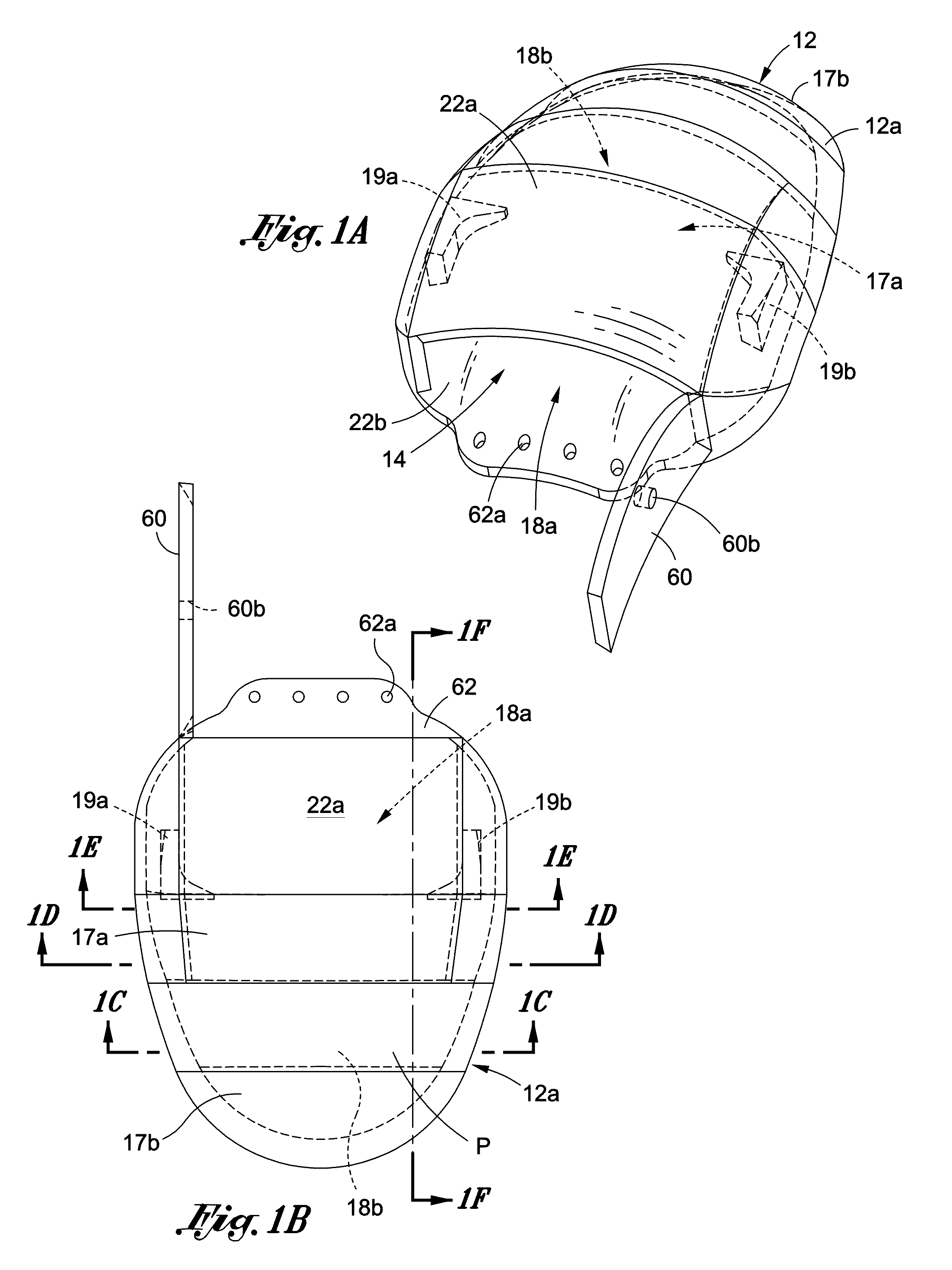
[0020]FIG. 1A is a perspective view of a cover for one embodiment of my implantable medical assembly.

[0021]FIG. 1B is a top plan view of the cover shown in FIG. 1A.

[0022]FIG. 1C is a cross-sectional view taken along line 1C-1C of in FIG. 1B.

[0023]FIG. 1D is a cross-sectional view taken along line 1D-1D of in FIG. 1B.

[0024]FIG. 1E is a cross-sectional view taken along line 1E-1E of in FIG. 1B.

[0025]FIG. 1F is a cross-sectional view taken along line 1F-1F of in FIG. 1B.

[0026]FIG. 2 is an exploded perspe...


PUM


Abstract

An implantable medical assembly includes a cover having a porous chamber. Enclosed within the chamber is a medical device through which aqueous body fluid flows from an outlet of the device into the chamber. The chamber is formed at least in part from a porous material that promotes vascularization and inhibits fibrotic encapsulation upon implantation and that allows aqueous body fluid in the chamber to flow through the porous material into body tissue in which the assembly is implanted. The chamber has a pair of walls that are spaced apart at a first portion of the chamber at or near the outlet and converge at a second portion of the chamber downstream of the outlet.

Description

BACKGROUND[0001]During trabeculectomy, or even glaucoma implant surgery, when aqueous humor is drained from the anterior chamber of the eye to the outside tissue, it causes a severe tissue reaction. One tissue reaction is to encapsulate the aqueous humor by means of fibrous tissue growth commonly known as bleb formation. Avoiding forming a bleb, or minimizing the rate of growth of a bleb around an implanted medical device, especially a glaucoma valve, is highly desirable. After the bleb is formed over an implanted glaucoma device, encapsulating it, the intraocular pressure (IOP) in the eye increases because the fluid in the bleb gets locked in. If the bleb is thin enough and there is sufficient blood vessel growth surrounding the fibrous tissue, the aqueous humor is then carried through the blood vessels back into circulation. Even though this phenomenon is helpful for aqueous transport from the bleb into the subcutaneous tissue, there is still resistance to aqueous flow from the ey...

Claims


Application Information

Patent Timeline
IPC IPC(8): A61M5/00
CPCA61F9/00781A61M5/00A61M5/14276A61F2250/0023A61F9/0017A61F2250/0003B33Y80/00
Inventor AHMED, A., MATEEN
Owner AHMED A MATEEN
Why Eureka
Try Eureka