Eureka AIR delivers breakthrough ideas for toughest innovation challenges, trusted by R&D personnel around the world.

Negative-working lithographic printing plate precursors with IR dyes

a technology of lithographic printing plate and precursor, which is applied in the field of negative-working lithographic printing plate precursor, can solve the problems of reducing the shelf life of imageable layer composition, cationic cyanine dye, and precursors with a strong tendency to crystallize, and achieve excellent imaging speed and the tendency of crystallization of cationic cyanine dy

Active Publication Date: 2014-01-21
EASTMAN KODAK CO
View PDF22 Cites 38 Cited by
  • Summary
  • Abstract
  • Description
  • Claims
  • Application Information

AI Technical Summary

Benefits of technology

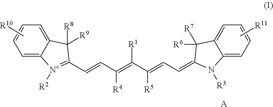
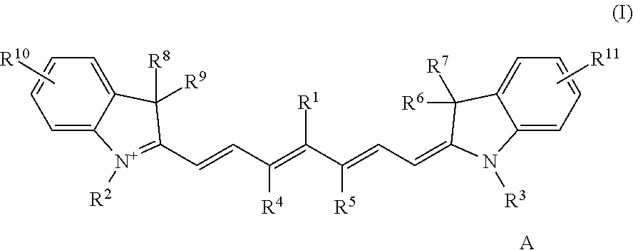
[0026]The lithographic printing plate precursors of this invention have excellent imaging speed and the tendency of crystallization of cationic cyanine dyes in the presence of tetraaryl borate anions is considerably reduced. These advantages are achieved by using a select class of cyanine dyes as infrared radiation absorbing dyes as defined by Structure (1) above.

Problems solved by technology

However, many of the cationic cyanine dyes that are used as infrared radiation absorbers in such lithographic printing plate precursors exhibit a strong tendency to crystallize in the presence of borate anions that can be in the imaging formulations.
This crystallization leads to reduced shelf life of the imageable layer composition in the lithographic printing plate precursor before the precursor is imaged.
The crystallization also leads to problems during manufacturing of the imageable layer formulations.

Method used


Image

  • Negative-working lithographic printing plate precursors with IR dyes
  • Negative-working lithographic printing plate precursors with IR dyes
  • Negative-working lithographic printing plate precursors with IR dyes

Examples


embodiment 1

[0164]2. The lithographic printing plate precursor of embodiment 1 wherein L is a sulfur or nitrogen linking atom, and Rx represents a carbocyclic or heterocyclic aromatic group, a heterocyclic non-aromatic group, or an alkyl group having 1 to 12 carbon atoms, which carbocyclic or heterocyclic aromatic, heterocyclic non-aromatic, or alkyl group comprises one or more ethylenically unsaturated polymerizable groups.

[0165]3. The lithographic printing plate precursor of embodiment 1 or 2 wherein L is a single connecting bond, and Rx is a group represented by the following Structure (II) wherein Y is oxygen or sulfur, and Ry and Rz are the same or different organic groups as described for Rx, at least one of which comprises one or more ethylenically unsaturated polymerizable groups:

[0166]

[0167]4. The lithographic printing plate precursor of any of embodiments 1 to 3 wherein Rx comprises a mercapto-functionalized thiazole or thiadiazole group and one or more ethylenically unsaturated polym...

embodiment 15

[0181]16. The method of embodiment 15 comprising processing the imaged precursor off-press using a processing solution.

[0182]17. The method of embodiment 15 comprising processing the imaged precursor on-press using a lithographic printing ink, a fountain solution, or both a lithographic printing ink and a fountain ink.

[0183]19. The method of any of embodiments 15 to 18 comprising imagewise exposing the lithographic printing plate precursor using radiation having a λmax of at least 700 nm and up to and including 1400 nm.

[0184]The following Examples are provided to illustrate the practice of this invention and are not meant to be limiting in any manner. The components and materials used in the examples were as follows:

[0185]BLO represents γ-butyrolactone.

[0186]Byk® 307 is a polyethoxylated dimethyl polysiloxane that is available from Byk Chemie.

[0187]CD9053 is an adhesion promoter that is available from Sartomer.

[0188]Developing Solution A contained 7.14 g of phenoxy ethanol, 1.71 g o...


PUM

PropertyMeasurementUnit
weight %aaaaaaaaaa
thicknessaaaaaaaaaa
thicknessaaaaaaaaaa

Abstract

A lithographic printing plate precursor comprises an imageable layer comprising a free radically polymerizable component, an initiator composition capable of generating free radicals upon exposure to imaging infrared radiation, an infrared radiation absorbing dye that is defined by Structure (I) shown in the disclosure, which dyes comprise one or more ethylenically unsaturated polymerizable groups in an organic group that is attached to the methine chain. These infrared radiation absorbing dyes exhibit a reduced tendency to crystallize in the imageable layers in the presence of tetraaryl borate counter anions and therefore provide improved shelf life.

Description

RELATED APPLICATION[0001]Reference is made to copending and commonly assigned U.S. Ser. No. 13 / 239,435, filed Sep. 22, 2011 by Balbinot et al., and entitled NEGATIVE-WORKING LITHOGRAPHIC PRINTING PLATE PRECURSORS.FIELD OF THE INVENTION[0002]This invention relates to negative-working lithographic printing plate precursors comprising unique infrared radiation absorber dyes, which lithographic printing plate precursors have high imaging speed and improved shelf-life. This invention also relates to a method for preparing lithographic printing plates.BACKGROUND OF THE INVENTION[0003]In lithographic printing, ink receptive regions, known as image areas, are generated on a hydrophilic surface. When the surface is moistened with water and ink is applied, the hydrophilic regions retain the water and repel the ink, while the ink receptive regions accept the ink and repel the water. The ink is then transferred to the surface of suitable materials upon which the image is to be reproduced. In so...

Claims


Application Information

Patent Timeline
Patent Type & Authority Patents(United States)
IPC IPC(8): B41N1/00B41M5/00G03F7/26G03F7/00
CPCG03F7/033G03F7/029G03F7/031G03F7/027G03F7/3035B41C1/10G03F7/004B41C2210/04B41C2210/22B41C2210/06B41C1/1008
Inventor BALBINOT, DOMENICOBAUMANN, HARALDDWARS, UDOJAREK, MATHIASMATZ, JAMES R.SIMPSON, CHRISTOPHER D.
Owner EASTMAN KODAK CO
Why Eureka
Eureka Blog
Learn More