
Enhancement of the channel propagation matrix order and rank for a wireless channel

Active Publication Date: 2014-02-11
COMS IP HLDG LLC
View PDF61 Cites 106 Cited by
  • Summary
  • Abstract
  • Description
  • Claims
  • Application Information

AI Technical Summary

Benefits of technology

The invention solves the problem of a line-of-sight propagation path in a MIMO radio configuration, allowing for a single stream or multiple MIMO streams in environments where the signal strength at a receiving radio is insufficient. The invention also provides a method for enhancing the wireless propagation environment, allowing for a piecewise line-of-sight, non-line-of-sight, or non-line-of-sight operation, where multiple segments of a particular link are utilized to provide a point-to-point-like propagation environment, avoiding obstructions. The invention also provides a repeater device for repeating one or more of the first information streams, a detector for performing detection of the first embedded control signals, a repeater device controller for enabling one or more transmitters of the repeater device, a demodulator for demodulating the first embedded control signals, a modulator for generating the second embedded control signals, a coupler for combining the second embedded control signals with the first information streams, a transmitter for transmitting the composite signal, and a detector for performing detection of the second embedded control signals. The performance of the MIMO wireless communication system is enhanced based upon adjustment of parameters associated with the repeater device and based upon information within the first control information.

Problems solved by technology

While deployment of optical fiber to an edge of the core data network would be advantageous from a network performance perspective, it is often impractical to connect all high bandwidth data networking points with optical fiber at all times. Instead, connections to remote edge access networks from core networks are often achieved with wireless radio, wireless infrared, and / or copper wireline technologies.
However, cellular base stations or WLAN access points inevitably become very high data bandwidth demand points that require continuous connectivity to an optical fiber core network.
These backhaul requirements cannot be practically satisfied at ranges of 300 m or more by existing copper wireline technologies.
Even if LAN technologies such as Ethernet over multiple dedicated twisted pair wiring or hybrid fiber / coax technologies such as cable modems are considered, it is impractical to backhaul at such data rates at these ranges (or at least without adding intermediate repeater equipment).
Such alignment is almost impossible to maintain over extended periods of time unless the two radios have a clear unobstructed line of sight (LOS) between them over the entire range of separation.
Furthermore, such precise alignment makes it impractical for any one such microwave backhaul radio to communicate effectively with multiple other radios simultaneously (i.e., a “point-to-multipoint” (PMP) configuration).
Although impressive performance results have been achieved for edge access, such results are generally inadequate for emerging backhaul requirements of data rates of 100 Mb / s or higher, ranges of 300 m or longer in obstructed LOS conditions, and latencies of 5 ms or less.
In particular, “street level” deployment of cellular base stations, WLAN access points or LAN gateways (e.g., deployment at street lamps, traffic lights, sides or rooftops of single or low-multiple story buildings) suffers from problems because there are significant obstructions for LOS in urban environments (e.g., tall buildings, or any environments where tall trees or uneven topography are present).
The conventional PTP radio on a whole is completely unsuitable for obstructed LOS PTP or PMP operation.
One such system is IEEE802.11n for use in home networking Attempts have been made to utilize MIMO and spatial multiplexing in line of sight environments having minimal scattering, which have generally been met with failure, in contrast to the use of cross polarized communications.
For example IEEE802.11n based Mesh networked nodes deployed at streetlight elevation in outdoor environments often experience very little benefit from the use of spatial multiplexing due to the lack of a rich multipath propagation environment.
Additionally, many of these deployments have limited range between adjacent mesh nodes due to physical obstructions resulting in the attenuation of signal levels.
For example, at specific receiver and transmitter frequency channel separation, the frequency selectivity of the channel selection filters in an IBR transmitter and receiver chains may be insufficient to isolate the receiver(s) from the transmitter signal(s) or associated noise and distortion, resulting in significant de-sensitization of the IBR's receiver(s) performance at specific desired transmit power levels, with out the use of disclosed ZDD techniques.
While this condition is necessary, it is not sufficient.
Such a condition often occurs in environments where a small angular spread at the desired intended receiver is present, such as is the case with a line-of-sight environment where the two MIMO stations are a significant distance apart, such that the angular resolution of the receiving antennas at MIMO Station 410 is insufficient to resolve and separate the signals transmitted from the plurality of transmitters at MIMO Station 405.
Such invertability, as previously mentioned, may be compromised by the receiving antenna correlation, which may be caused by close antenna spacing or small angular spread at the intended MIMO receiver.
The line-of-sight condition between two MIMO stations may result in such a small angular spread between the MIMO receivers, resulting in the channel matrix being noninvertible or degenerate.
Such a matrix is noninvertible and ill-conditioned, resulting in the inability to support spatial multiplexing and additional streams (other than by the use of polarization multiplexing, which provides for only 2 streams as discussed).

Method used


Image

  • Enhancement of the channel propagation matrix order and rank for a wireless channel
  • Enhancement of the channel propagation matrix order and rank for a wireless channel
  • Enhancement of the channel propagation matrix order and rank for a wireless channel

Examples


Embodiment Construction

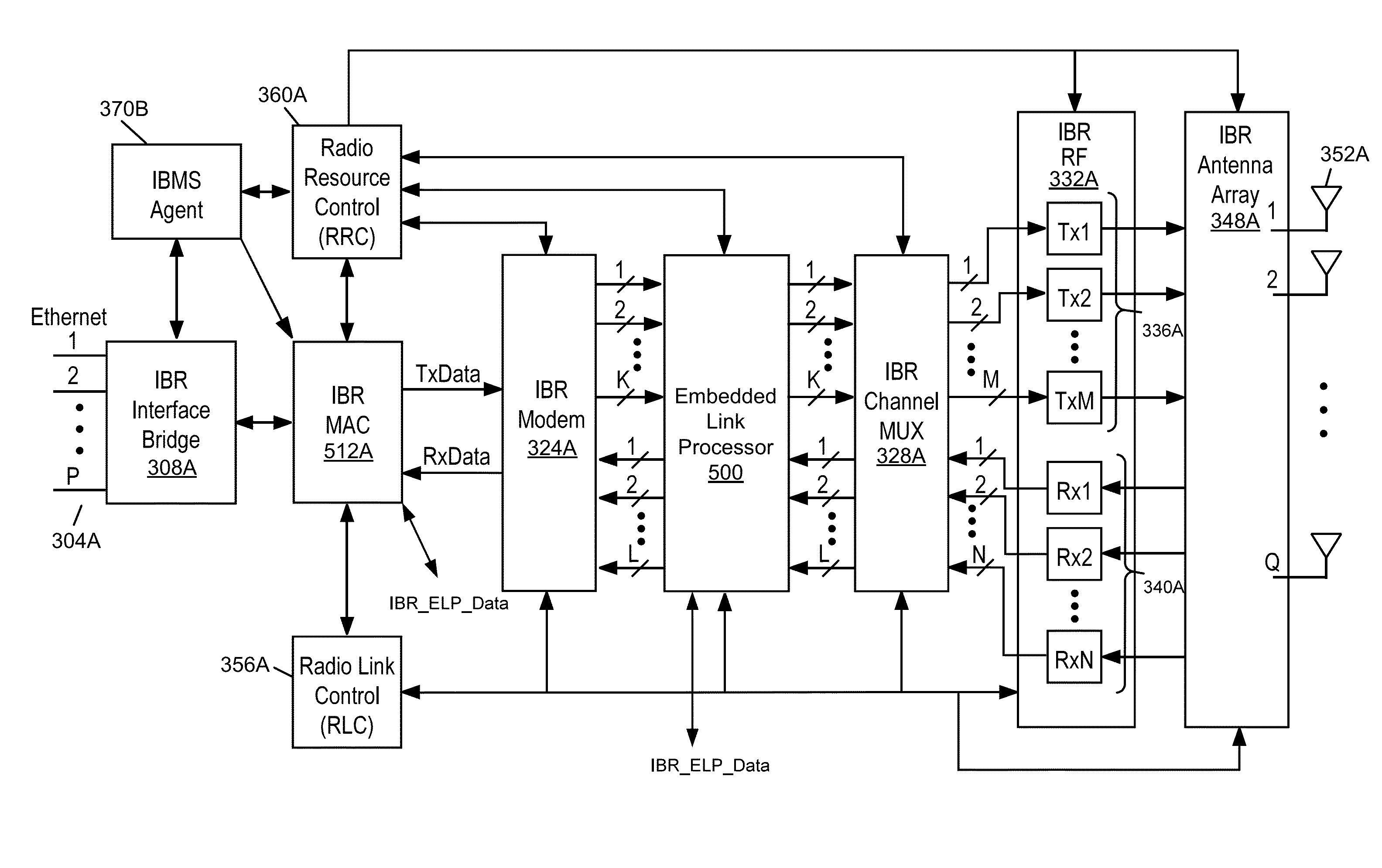
[0113]Referring now to FIG. 5A, an embodiment of an IBR including an Embedded Link Processor (ELP) is depicted. A number of the blocks common with FIG. 3B are shown, whose functioning is generally described associated with the foregoing description. Relative to FIG. 3B, FIG. 5A provides for a modified IBR MAC 512A, and an additional block referred to as an Embedded Link Processor (ELP) 500.

[0114]Embodiments of IBR MAC 512A generally incorporate the functionality of the various embodiments of IBR MAC 312A. Some Embodiments of IBR MAC 512A additionally include MAC processing supporting the optimization of the wireless links utilizing ECHO devices. Additionally some embodiments of IBR MAC 512A support peer to peer and communications with other devices (e.g. ECHO devices) utilizing an embedded control channel for the transfer of control information.

[0115]Embodiments of the Embedded Link Processor (ELP) 500 provide for the reception and insertion of an additional wireless communications ...


PUM


Abstract

Enhancement of wireless Channel Order and rank (ECHO) systems and ECHO repeater devices for enhancement of a wireless propagation channel for point to point or point to multipoint radio configurations are disclosed. The enhancement may be used for MIMO communications channels. Aspects support a richer multipath environment to increase the rank of the channel propagation matrix and / or to increase the magnitude of the coefficients of the propagation matrix between two or more radios. Such enhancement is applicable to backhaul radios in terms of increased range or in the number of supportable information streams. The installation, provisioning, optimization, control, monitoring, and adaptation of such devices within a network of backhaul radios is also disclosed. Wireless links and control between IBR and ECHO devices, and between ECHO devices and other ECHO devices, are also disclosed.

Description

BACKGROUND[0001]1. Field[0002]The present disclosure relates generally to data networking and in particular to a backhaul radio for connecting remote edge access networks to core networks.[0003]2. Related Art[0004]Data networking traffic has grown at approximately 100% per year for over 20 years and continues to grow at this pace. Only transport over optical fiber has shown the ability to keep pace with this ever-increasing data networking demand for core data networks. While deployment of optical fiber to an edge of the core data network would be advantageous from a network performance perspective, it is often impractical to connect all high bandwidth data networking points with optical fiber at all times. Instead, connections to remote edge access networks from core networks are often achieved with wireless radio, wireless infrared, and / or copper wireline technologies.[0005]Radio, especially in the form of cellular or wireless local area network (WLAN) technologies, is particularl...

Claims


Application Information

Patent Timeline
IPC IPC(8): H04B3/36
CPCH04B3/36H04B7/0413H04B7/10H04B7/15H04B7/0486H04B7/15592H04B7/08H04L27/38H04W72/0453
Inventor NEGUS, KEVIN J.PROCTOR, JR., JAMES A.
Owner COMS IP HLDG LLC
Learn More