Electromechanical transducer and method of manufacturing the same
a transducer and electromechanical technology, applied in the field of electromechanical transducers, can solve the problems of reducing the stiffness of the transducer array, oxidizing the monocrystalline silicon diaphragm, and breaking the transducer array, so as to prevent the lowering of the stiffness of the transducer, reduce the thickness fluctuation, and reduce the residual stress
- Summary
- Abstract
- Description
- Claims
- Application Information
AI Technical Summary
Benefits of technology
Problems solved by technology
Method used
Image
Examples
example 1
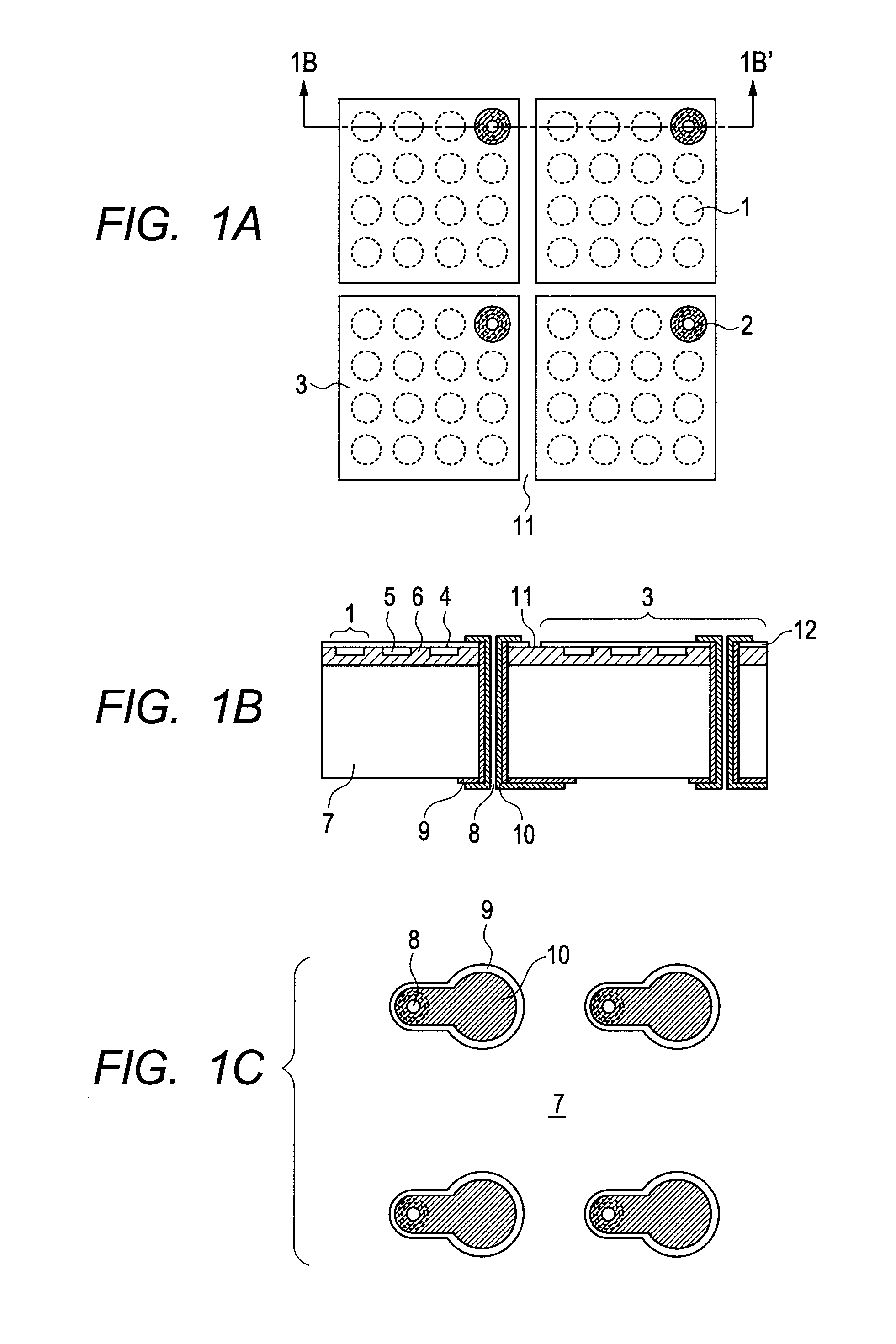
[0060]A configuration of a capacitive transducer array of Example 1 is described with reference to FIGS. 1A to 1C used in describing the above-mentioned first embodiment. In this example, too, the capacitive transducer array includes multiple elements 3 each including multiple cellular structures 1 and through wiring 2. In FIG. 1A, only four of the elements 3 are illustrated, but arbitrary number of the elements 3 may be arranged.
[0061]The cellular structure 1 includes a monocrystalline silicon diaphragm 4 having a thickness of 1 μm, a gap 5, a diaphragm supporting portion 6 for supporting the monocrystalline silicon diaphragm 4 having a resistivity of 0.01 Ω·cm, and a silicon substrate 7. The silicon substrate 7 has a thickness of 300 μm and a resistivity of 0.01 Ω·cm. The cellular structure 1 illustrated in FIGS. 1A to 1C is in the shape of a circle, but may be in the shape of a square, a hexagon, or the like. A main material of the monocrystalline silicon diaphragm 4 is monocryst...
example 2
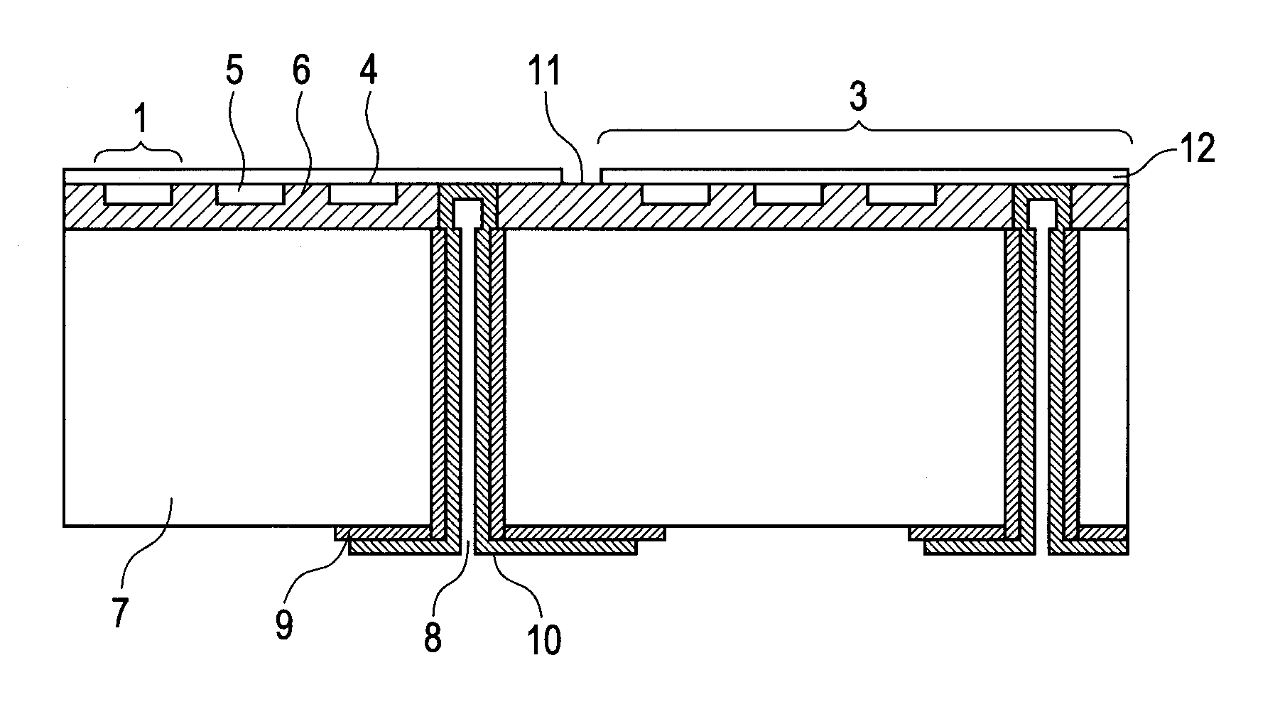
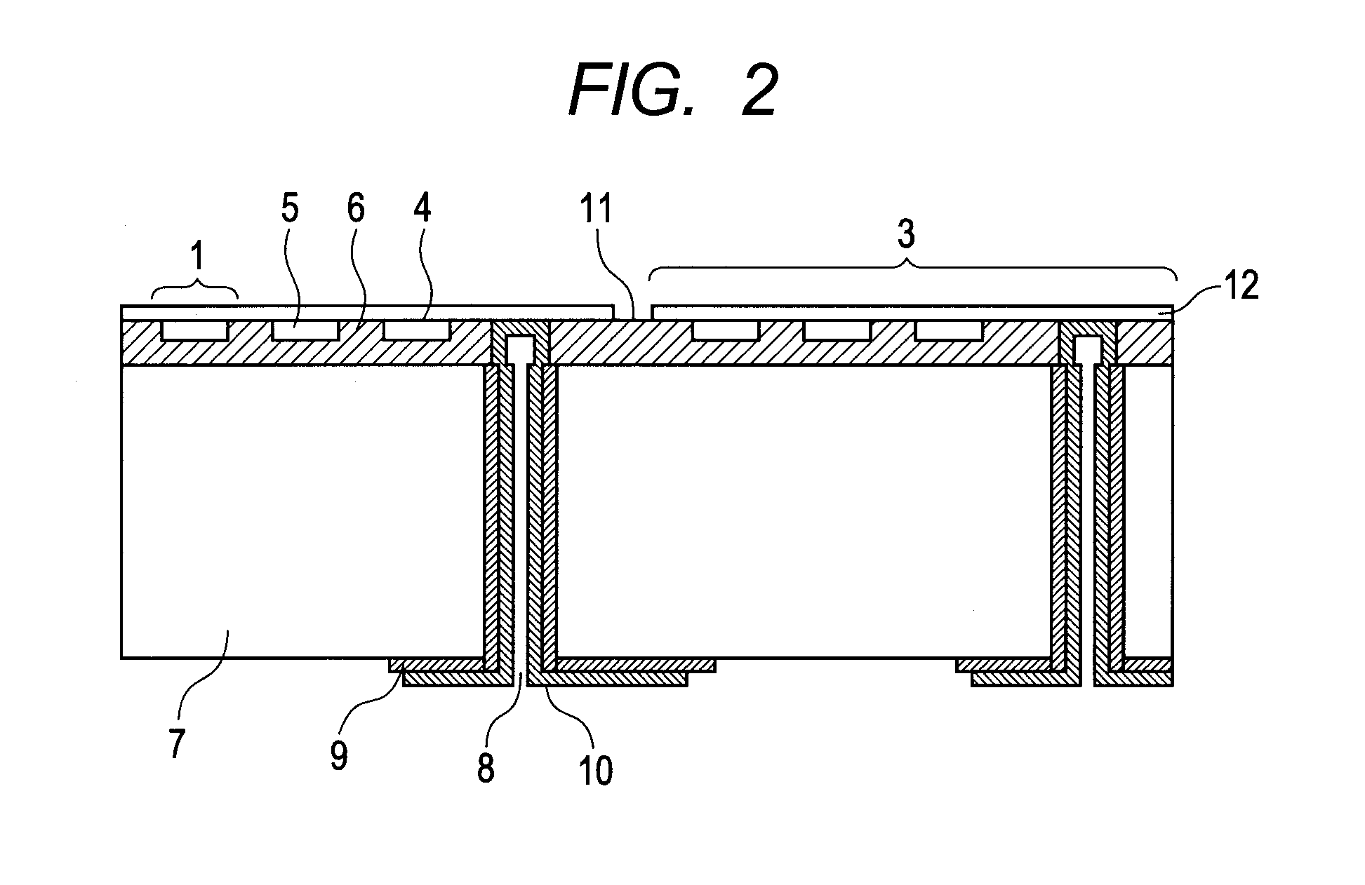
[0067]A configuration of a capacitive transducer array of Example 2 is described with reference to FIG. 2. FIG. 2 is a sectional view of the capacitive ultrasound transducer array of this example. The configuration of Example 2 is substantially similar to that of Example 1.
[0068]A cellular structure 1 includes a monocrystalline silicon diaphragm 4 having a thickness of 1 μm, a gap 5, a diaphragm supporting portion 6 for supporting the monocrystalline silicon diaphragm 4, and a silicon substrate 7. The silicon substrate 7 has a thickness of 300 μm and a resistivity of 0.01 Ω·cm. In this configuration, the cellular structure 1 is in the shape of a circle with the diameter of 40 μm. The diaphragm supporting portion 6 is formed of silicon oxide and has a height of 400 nm. The amount of the gap 5 is 200 nm. The through wiring 2 includes a through hole 8, a conductor 10, and an insulating layer 9 for insulating the side wall of the through hole 8 and a part of the silicon substrate 7 from...
example 3
[0070]A method of manufacturing a capacitive transducer array of Example 3 is described with reference to FIGS. 3A to 3F used in describing the above-mentioned first embodiment. As illustrated in FIG. 3A, an insulating layer 31 which is silicon oxide is formed by thermal oxidation on a first silicon substrate 30 having a thickness of 300 μm, and a gap 32 is formed by photolithography or etching. The resistivity of the first silicon substrate 30 is on the order of 0.01 Ω·cm.
[0071]Then, as illustrated in FIG. 3B, a second silicon substrate 33 is bonded and thinned. Here, the second silicon substrate 33 is an SOI substrate. In the SOI substrate, an active layer 34 has a thickness of 1 μm, a BOX layer 35 has a thickness of 0.4 μm, and a handle layer 36 has a thickness of 525 μm. The active layer 34 in the SOI substrate has a resistivity of 0.1 Ω·cm. The active layer 34 having thickness fluctuations of ±5% or less is used, and the active layer side is directly bonded. The active layer in...
PUM
 Abstract
Description
Claims
Application Information
 - R&D
- Intellectual Property
- Life Sciences
- Materials
- Tech Scout
- Unparalleled Data Quality
- Higher Quality Content
- 60% Fewer Hallucinations
Browse by: Latest US Patents, China's latest patents, Technical Efficacy Thesaurus, Application Domain, Technology Topic, Popular Technical Reports.
© 2025 PatSnap. All rights reserved.Legal|Privacy policy|Modern Slavery Act Transparency Statement|Sitemap|About US| Contact US: help@patsnap.com


