Exhaust gas treating method

a gas treatment method and exhaust gas technology, applied in the direction of separation processes, hydrogen sulfides, sulfur compounds, etc., can solve the problems of emitted hgsup>(0) /sup>, additives such as fixing agents are not effectively exploited, and the removal rate cannot be stably maintained, so as to achieve stably and efficiently remove the

Active Publication Date: 2014-03-04
CHIYODA CORP
View PDF21 Cites 29 Cited by
  • Summary
  • Abstract
  • Description
  • Claims
  • Application Information

AI Technical Summary

Benefits of technology

[0009]As pointed out above, the known techniques of removing mercury in exhaust gas with sulfur dioxide are accompanied by problems including that a high removal rate cannot be stably maintained for a long period of time in addition to a problem that the oxidizing agent for oxidizing mercury is consumed to oxidize sulfur dioxide so as to be lost to a large extent, that the additives such as a fixing agent are not exploited effectively and that Hg(0) is emitted again from the absorption liquid due to insufficient oxidation of mercury. Therefore, the object of the present invention is to provide an exhaust gas treating method that can comprehensively dissolve these problems and stably maintain a high removal rate for sulfur dioxide and mercury stably for a long period of time if the load of power generation and the composition of exhaust gas fluctuate.

Problems solved by technology

As pointed out above, the known techniques of removing mercury in exhaust gas with sulfur dioxide are accompanied by problems including that a high removal rate cannot be stably maintained for a long period of time in addition to a problem that the oxidizing agent for oxidizing mercury is consumed to oxidize sulfur dioxide so as to be lost to a large extent, that the additives such as a fixing agent are not exploited effectively and that Hg(0) is emitted again from the absorption liquid due to insufficient oxidation of mercury.
However, such a technique is accompanied by the above identified problems and the inventors of the present invention have found that the Hg(0) removal rate is not improved significantly simply by adding KI or KBr to absorption liquid.
Furthermore, when KI or KBr is added at a high rate, the discharged gas contains iodine or bromine, whichever appropriate, to a large extent to give rise to a problem of secondary pollution.

Method used


Image

  • Exhaust gas treating method
  • Exhaust gas treating method
  • Exhaust gas treating method

Examples


example 1

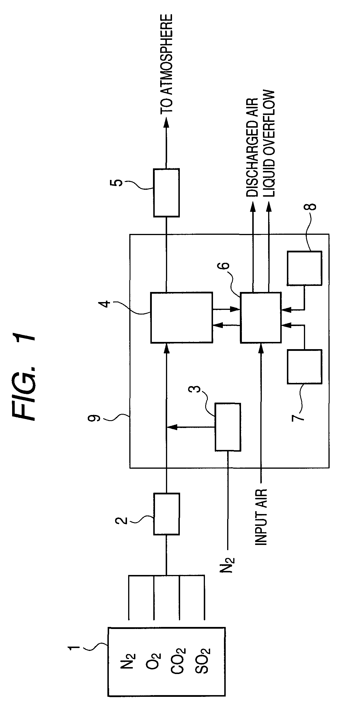
[0044]An experiment of removing sulfur dioxide and mercury from simulated exhaust gas was conducted by using the labo test unit of FIG. 1. Mixture gas containing SO2 to a concentration of 1,000 ppm, O2 to a concentration of 5 vol %, CO2 to a concentration of 10 vol % and N2 taking the balance was supplied from the gas supply section 1 at a rate of 100 NL / hour and warmed and humidified to sufficiently contain moisture at 50° C. in the gas warming / humidifying section 2. Then, N2 was introduced into the mercury generating section 3 at a rate of 0.2 NL / hour to generate mercury vapor, which mercury vapor was added to the humidified mixture gas to produce simulated exhaust gas containing Hg(0) to a concentration of about 30 ppb. The produced simulated exhaust gas was then brought into contact with absorption liquid in the gas / liquid contact section 4 and the simulated exhaust gas was sampled both before and after the gas / liquid contact section 4 to observe the mercury concentration in the...

example 2

[0049]An experiment of removing sulfur dioxide and mercury from simulated exhaust gas was conducted by using the labo test unit of FIG. 1. Mixture gas containing SO2 to a concentration of 1,000 ppm, O2 to a concentration of 5 vol %, CO2 to a concentration of 10 vol % and N2 taking the balance was supplied from the gas supply section 1 at a rate of 100 NL / hour and humidified to sufficiently contain moisture at 50° C. in the gas warming / humidifying section 2. Then, N2 was introduced into the mercury generating section 3 at a rate of 0.2 NL / hour to generate mercury vapor, which mercury vapor was added to the humidified mixture gas to produce simulated exhaust gas containing Hg(0) to a concentration of about 30 ppb. The produced simulated exhaust gas was then brought into contact with absorption liquid in the gas / liquid contact section 4 and the simulated exhaust gas was sampled both before and after the gas / liquid contact section 4 to observe the mercury concentration and the concentra...

example 3

[0053]The experiment of this example was conducted under conditions same as those of Example 2 except that HgCl2 was added to exhaust gas to a concentration of 30 ppb and KI was added to the absorption liquid to a concentration of 2 mmol / L. However, a value of air 15 L / hour was selected for the aeration rate and the ORP was 400 to 600 mV under that condition.

[0054]Apart from this example, an experiment was conducted in a comparative example under the same conditions as those of this example except that absorption liquid that contained neither Na2S2O8 nor KI was employed and a value of air 40 L / hour was selected for the aeration rate. The observed desulfurization rate was not less than 90% but practically no Hg(0) could be removed.

[0055]Thus, it was found that the arrangement of this example could maintain a desulfurization rate of not less than 90%, an Hg(0) removal rate of not less than 75% and an HgCl2 removal rate of not less than 90% over 100 hours with an amount of air used for...


PUM

PropertyMeasurementUnit
concentrationaaaaaaaaaa
temperatureaaaaaaaaaa

Abstract

An exhaust gas treating method removes sulfur dioxide from exhaust gas containing at least sulfur dioxide and mercury by bringing the exhaust gas into contact with absorption liquid. Persulfate is added into the absorption liquid or alternatively, iodine gas is added to the exhaust gas before the exhaust gas is brought into contact with the absorption liquid. A high removal rate for both sulfur dioxide and mercury is stably maintained if the load of power generation and the composition of exhaust gas fluctuate.

Description

TECHNICAL FIELD[0001]The present invention relates to an exhaust gas treating method. More particularly, the present invention relates to a method of removing sulfur dioxide and mercury from exhaust gas containing them.BACKGROUND ART[0002]Combustion exhaust gas (to be referred to as “exhaust gas” hereinafter) discharged from boilers in thermoelectric power stations and waste incinerators generally contains sulfur dioxide (SO2). Sometimes, it also contains mercury to a high-concentration level depending on the type of fossil fuel (coal in particular) and the types of wastes that are burnt there. Since those substances are harmful substances that adversely affect the health of inhabitants if discharged into the environment, they need to be removed before exhaust gas is emitted into the atmosphere from those facilities. Of the above listed substances, sulfur dioxide has been and being required to be removed by exhaust gas release control regulations. Recently, regulations for compulsor...

Claims


Application Information

Patent Timeline
Patent Type & Authority Patents(United States)
IPC IPC(8): B01D53/14C01B15/06B01D47/00C01B7/00
CPCB01D53/64B01D2251/106B01D2257/108B01D2257/602B01D2257/302B01D53/78B01D53/1456B01D53/34B01D53/50B01D53/77
Inventor KAWAMURA, KAZUSHIGETAKEDA, DAIAWAI, EIJIKUMAGAI, AKIRA
Owner CHIYODA CORP
Why Eureka
Try Eureka