Burner for highly caking coal, and gasifier

a high-caking coal and burner technology, applied in the direction of gasifier mechanical details, combustion types, combustion failure safe, etc., can solve the problems of blockage of the burner, problems not only with the burner that uses solid fuels, but also with the burner of the gasifier, so as to prevent or suppress fusion and expansion, reduce the temperature of the solid fuel, and expand the range of applications

Active Publication Date: 2014-03-11
MITSUBISHI POWER LTD
View PDF12 Cites 7 Cited by
  • Summary
  • Abstract
  • Description
  • Claims
  • Application Information

AI Technical Summary

Benefits of technology

[0017]The present invention was achieved in view of the foregoing circumstances, and it is an object of the invention to provide a burner for highly caking coal in which a solid fuel channel and a gasifying agent channel are provided in a double pipe structure, wherein the temperature increase of the particles of a highly caking solid fuel due to heat transfer in the burner and the resulting fusion and expansion of the particles are prevented or suppressed, thereby enabling a stable operation of the gasifier.
[0029]With the present invention described above, in a burner for highly caking coal used for a gasifier for gasifying a highly caking solid fuel, it is possible to prevent or suppress the fusion and expansion of the solid fuel particles that could be caused by the temperature increase of the solid fuel particles, due to heat transfer in the burner, which includes a solid fuel channel and a gasifying agent channel in a concentric double pipe structure. Accordingly, it is possible to prevent the problem that fused and expanded adjacent particles agglomerate due to the temperature increase of the highly caking solid fuel, thereby causing incomplete combustion, or the problem that those particles adhere to the internal surface of the solid fuel channel, thereby causing blockage. Accordingly, it is possible to operate the burner for highly caking coal and the gasifier in a stable manner. Furthermore, it is also possible to expand the range of applications for highly caking solid fuels that can be used for the burner for highly caking coal and the gasifier.

Problems solved by technology

At this time, when the solid fuel is highly caking, there may be the problem that the fused and expanded adjacent particles of the solid fuel agglomerate, thereby causing incomplete combustion, or the problem that the fused and expanded solid fuel adheres to the internal surface of the solid fuel channel 13, thereby causing blockage of the burner 12.
Such problems occur not only with burners that use solid fuels such as pulverized coal and petroleum coke, but also with burners of the gasifiers that use other highly caking solid fuels, including, for example, oil residue and plastics.

Method used


Image

  • Burner for highly caking coal, and gasifier
  • Burner for highly caking coal, and gasifier
  • Burner for highly caking coal, and gasifier

Examples


first embodiment

[0053

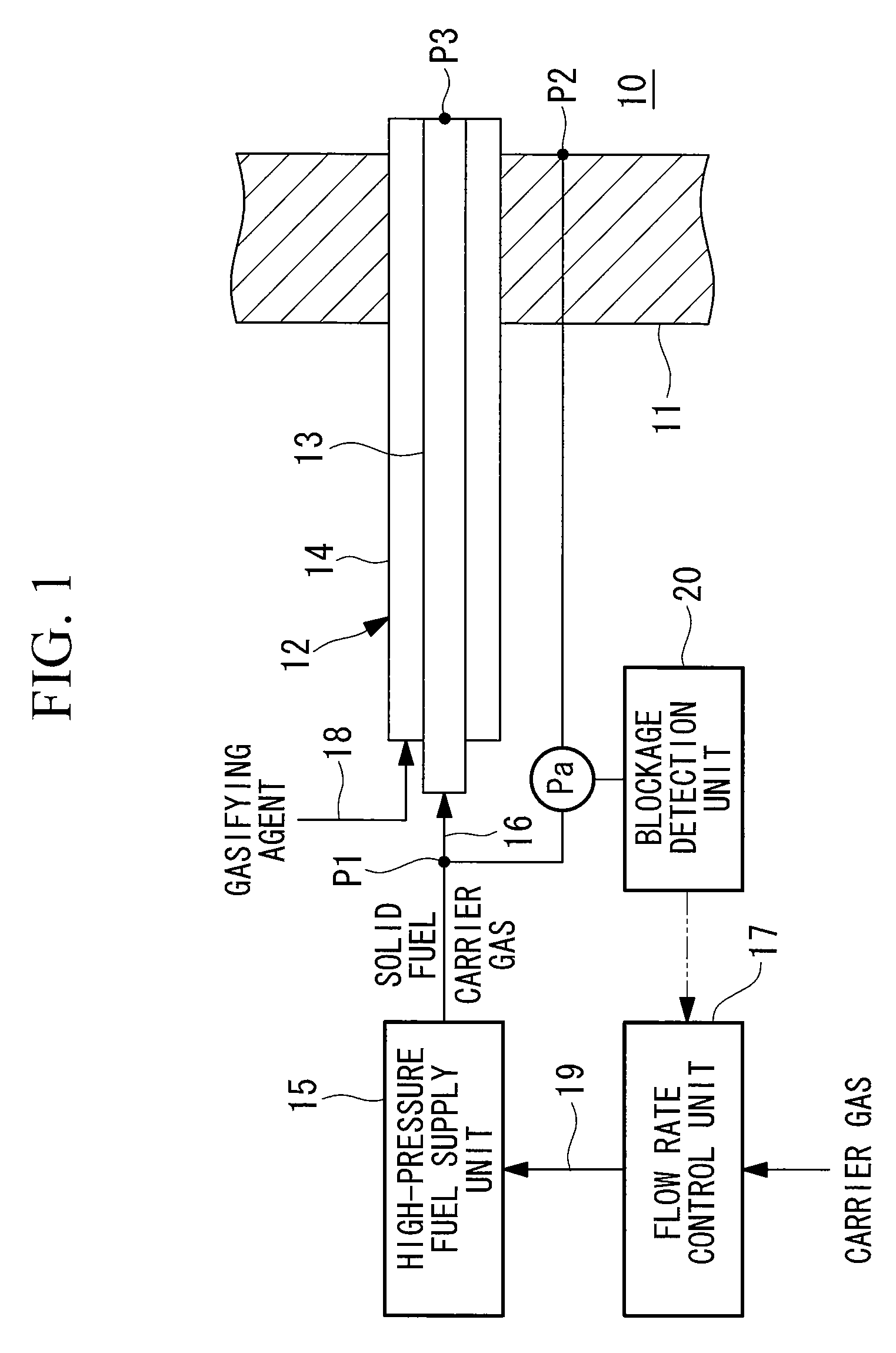
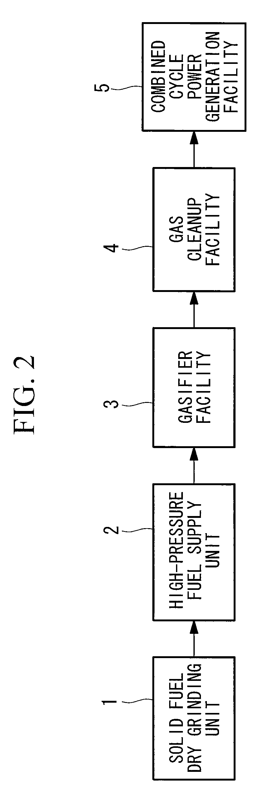
[0054]As shown in FIG. 1, the gasifier facility 3 of the IGCC described above is provided with a gasifier 10 in the form of a pressure vessel. A burner 12 for highly caking coal (hereinafter referred to as a “burner”) is attached to the gasifier 10 such that it penetrates through a surrounding wall 11, which is a furnace wall constituting the pressure vessel.

[0055]The burner 12 has a concentric double pipe structure including a solid fuel channel 13 that is disposed on the inner side, and a gasifying agent channel 14 that is disposed on the outside.

[0056]The solid fuel channel 13 is a fuel supply channel that supplies a highly caking solid fuel that has been pulverized into particles into the gasifier 10. The solid fuel channel 13 is connected with a high-pressure fuel supply unit 15 via a fuel supply line 16.

[0057]The high-pressure fuel supply unit 15 is an apparatus for receiving supply of the solid fuel pulverized into particles, and supplying the desired amount of the solid...

second embodiment

[0070

[0071]A second embodiment of the present invention will be described based on FIG. 4. It should be noted that the same portions in FIG. 4 as in the above-described embodiment are denoted by the same reference numerals, and a detailed description thereof has been omitted.

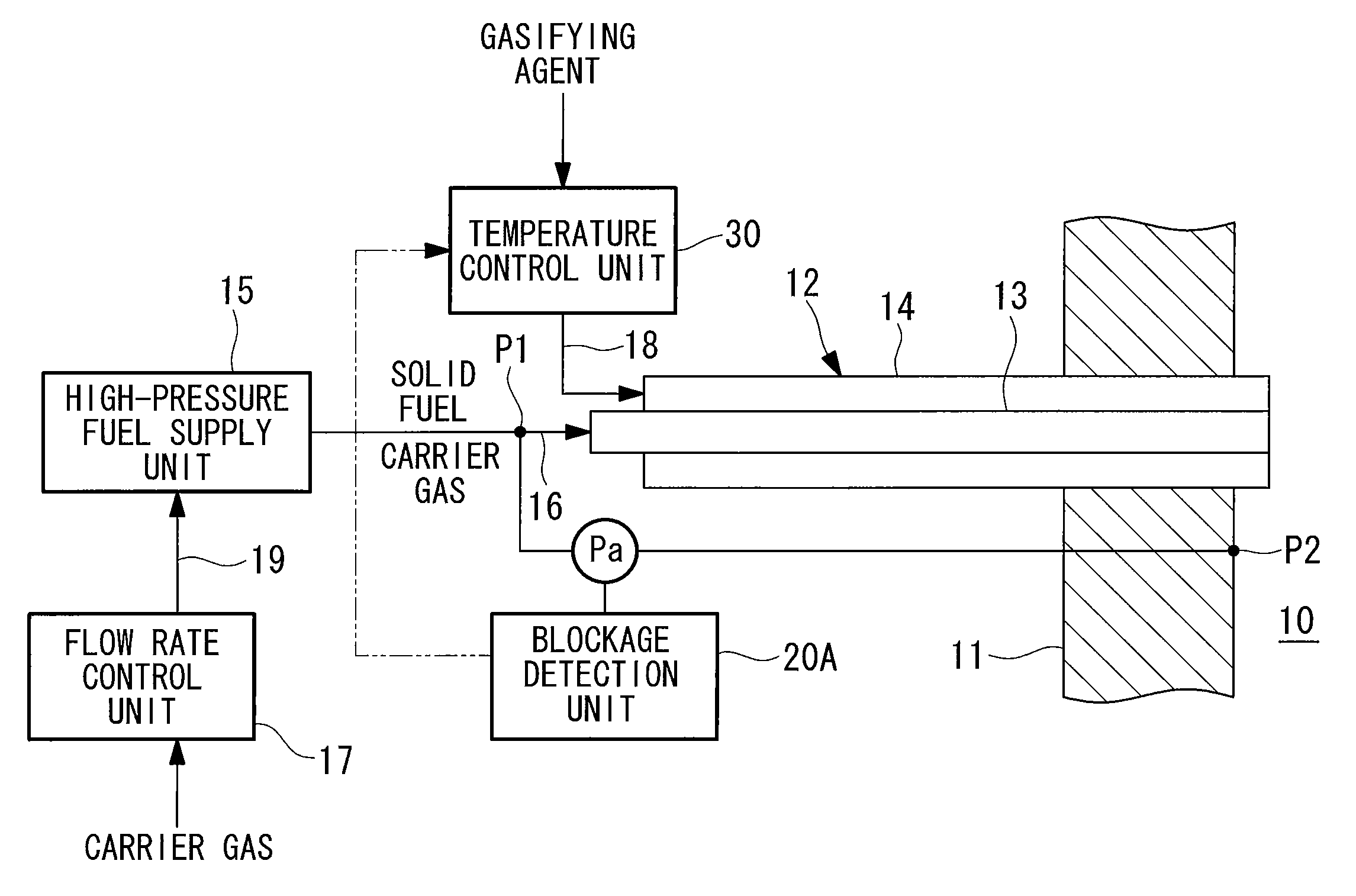
[0072]In this embodiment, when a blockage situation is detected, a different temperature reduction process is performed by a blockage detection unit 20A. That is, instead of increasing the amount of the carrier gas in the above-described embodiment, a temperature reduction process in which a control signal for decreasing the temperature of the gasifying agent is output is performed.

[0073]Hereinafter, the temperature reduction control by which the temperature of the gasifying agent is decreased will be described specifically. In order to enable this temperature reduction control, a temperature control unit 30 is provided in the gasifying agent supply line 18.

[0074]The temperature control unit 30 has the function ...

third embodiment

[0076

[0077]A third embodiment of the present invention will be described based on FIG. 5. It should be noted that the same portions in FIG. 5 as in the above-described embodiments are denoted by the same reference numerals, and a detailed description thereof has been omitted.

[0078]In this embodiment, a different blockage situation detection means that detects a blockage situation is used. That is, in place of a flow loss coefficient λ converted from a differential pressure Pa in the above-described embodiments, a flow loss coefficient λ′ converted based on a differential pressure ratio is used as a judgment criterion of a channel blockage situation.

[0079]More specifically, a blockage detection unit 20B serving as a blockage situation detection means in this embodiment judges that a blockage situation has been detected when a flow loss coefficient λ′ converted from the differential pressure ratio of a first differential pressure Pa detected between the pressure P1 at the burner inlet...


PUM

PropertyMeasurementUnit
temperatureaaaaaaaaaa
surface temperatureaaaaaaaaaa
pressureaaaaaaaaaa

Abstract

In a burner for highly caking coal in which a solid fuel channel that is attached penetrating through a surrounding wall of a gasifier for gasifying a highly caking solid fuel that has been pulverized into particles and that supplies the solid fuel into the gasifier by gas flow transportation, and a gasifying agent channel that supplies a gasifying agent into the gasifier are provided, a blockage detection unit that detects a blockage situation of the solid fuel channel is provided, and a process for reducing the temperature of the solid fuel is performed when the blockage detection unit detects a predetermined blockage situation.

Description

TECHNICAL FIELD[0001]The present invention relates to a burner for highly caking coal that is applied to a solid fuel gasifier or the like of an integrated coal gasification combined cycle facility, and to a gasifier.BACKGROUND ART[0002]Conventionally, so-called integrated coal gasification combined cycle power plants (IGCC) have been developed and put into practical use with the goal of improving the power generation efficiency of coal-fired power plants. Such an integrated coal gasification combined cycle power plant (hereinafter, referred to as an “IGCC”) includes a gas turbine generator that uses coal gas obtained by gasifying coal as a fuel, to operate and generate power, and a steam turbine generator that uses the steam obtained by recovering heat from high-temperature combustion exhaust gas discharged from the gas turbine using an exhaust heat recovery boiler, to operate and generate power.[0003]In such an IGCC, the fuel supply to the gasifier that generates the coal gas is p...

Claims


Application Information

Patent Timeline
Patent Type & Authority Patents(United States)
IPC IPC(8): C10J1/207F23N5/18F23K3/02F23D1/00F23N1/02
CPCC10J2200/152F23N2005/181Y02E20/16C10J2300/165C10J3/723C10J3/506F23D2900/00002C10J2300/093C10J2300/1687F23N5/18C10J2300/1892C10J2200/09F23N2031/26C10J2300/1675F23J9/00C10J2300/0956F23N5/242C10J3/466Y02E20/18F23D1/00F23N2231/26C10J3/46F23N5/24
Inventor KOYAMA, YOSHINORIARUGA, TAKESHIISHII, HIROMI
Owner MITSUBISHI POWER LTD
Why Eureka
Try Eureka