Supercharge Your Innovation With Domain-Expert AI Agents!

Air classifier

a classifier and air technology, applied in the field of air classifiers, can solve the problems of increasing the amount of ultra-fine powder, reducing the dispersion performance of conventional ds air classifiers, and reducing the classification accuracy, so as to achieve the effect of effective recycling of excessive toner, preventing contamination with coarse powder, and generating excessive fine powder

Active Publication Date: 2014-03-11
RICOH KK
View PDF53 Cites 1 Cited by
  • Summary
  • Abstract
  • Description
  • Claims
  • Application Information

AI Technical Summary

Benefits of technology

The present invention provides an air classifier that can prevent fine powder excess and contamination with coarse powder, recycle excessive fine powder, and improve classification accuracy. The air classifier has a fine powder discharge port and pipe to facilitate dispersion and collect ultra-fine powder. The toner produced has a sharp particle size distribution and high quality, ensuring high image quality without smears or improper transfer.

Problems solved by technology

When used to disperse such increased number of particles, the dispersion performance of conventional DS air classifiers will decrease, resulting in decreased classification accuracy.
This inevitably leads to an increase in the amount of ultra-fine powder caused by excessive pulverization and coarse particles contaminating the fine powder discharge unit.
As a result, the product obtained by the classification process may cause smears and improper transfer and may therefore lead to decreased image quality.
The increased amount of ultra-fine powder and the contamination of the fine powder discharge unit with coarse particles may also pose an excessive load on the classifier during the production process and may thus decrease the efficiency of classification as well as the energy efficiency of pulverization.
This construction is disadvantageous in that when raw materials are fed with high pressure air, the pressure difference within the dispersion chamber causes the raw materials to be released from the collector into the atmosphere, making it difficult to further continue the classification process.

Method used


Image

  • Air classifier
  • Air classifier
  • Air classifier

Examples


example 1

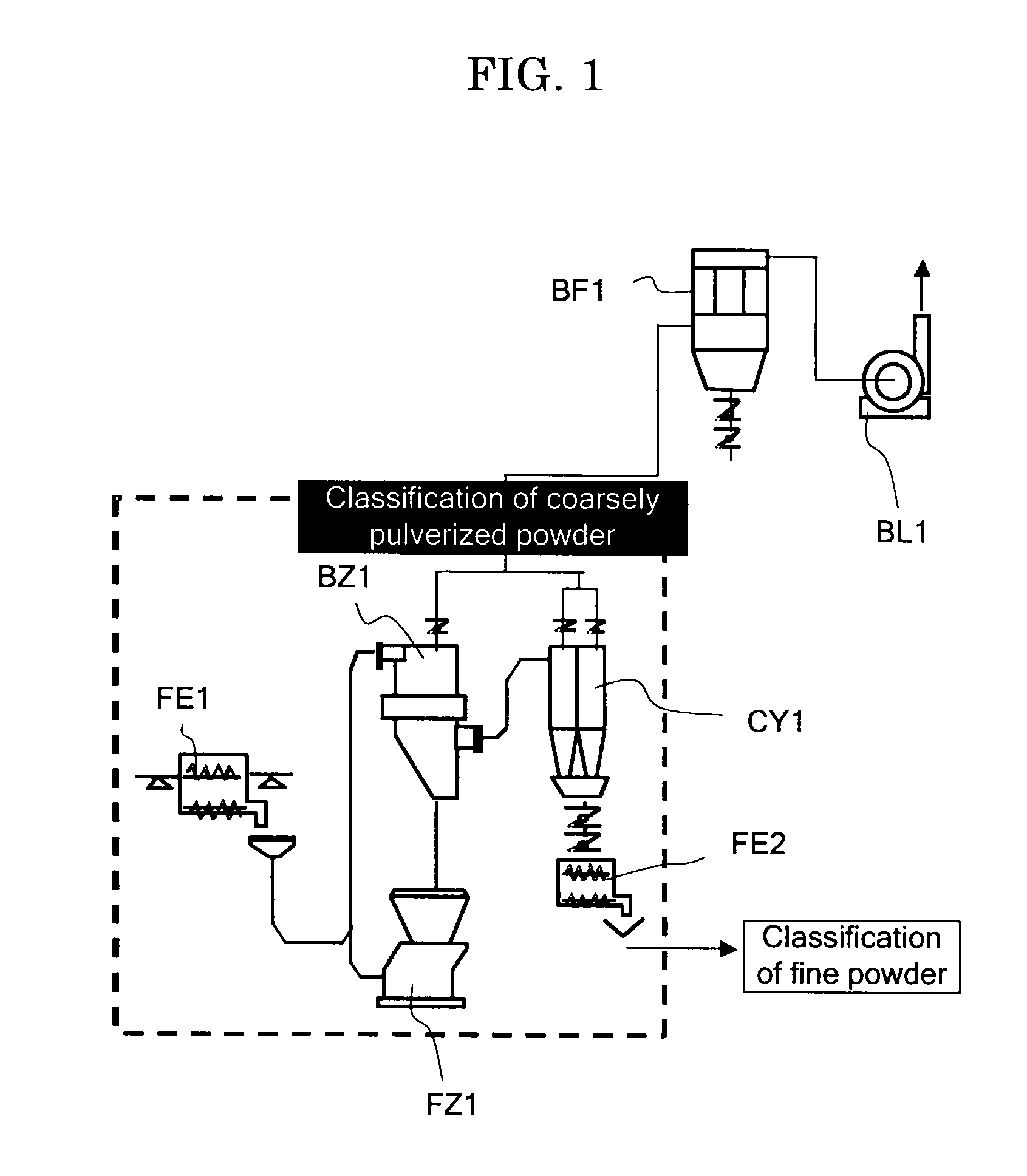
[0057]In the classification flow of coarsely pulverized powder shown in FIG. 2, an air classifier having the construction shown in FIGS. 5A and 5B was used as the air classifier BZ1 (the number N of the guide slats 1q of the louver ring 1Q=R / 30 (where R was the length (in mm) of the inner periphery of the casing of the dispersion chamber)) and an I-type mill pulverizer (manufactured by Nippon Pneumatic Mfg. Co., Ltd.) was used as the first pulverizer FZ1. A mixture of 75% by mass of a polyester resin, 10% by mass of a styrene-acryl copolymer resin and 15% by mass of carbon black was melted and kneaded in a roll mill. The mixture was then allowed to cool and solidified and the solidified mixture was coarsely pulverized in a hammer mill to form a raw toner material. This material was fed at a rate of 100 kg / hr in the classification flow to thereby yield a toner having a particle size distribution such that a weight average particle diameter was 4.5 μm, a fine particle (particle diamet...

example 2

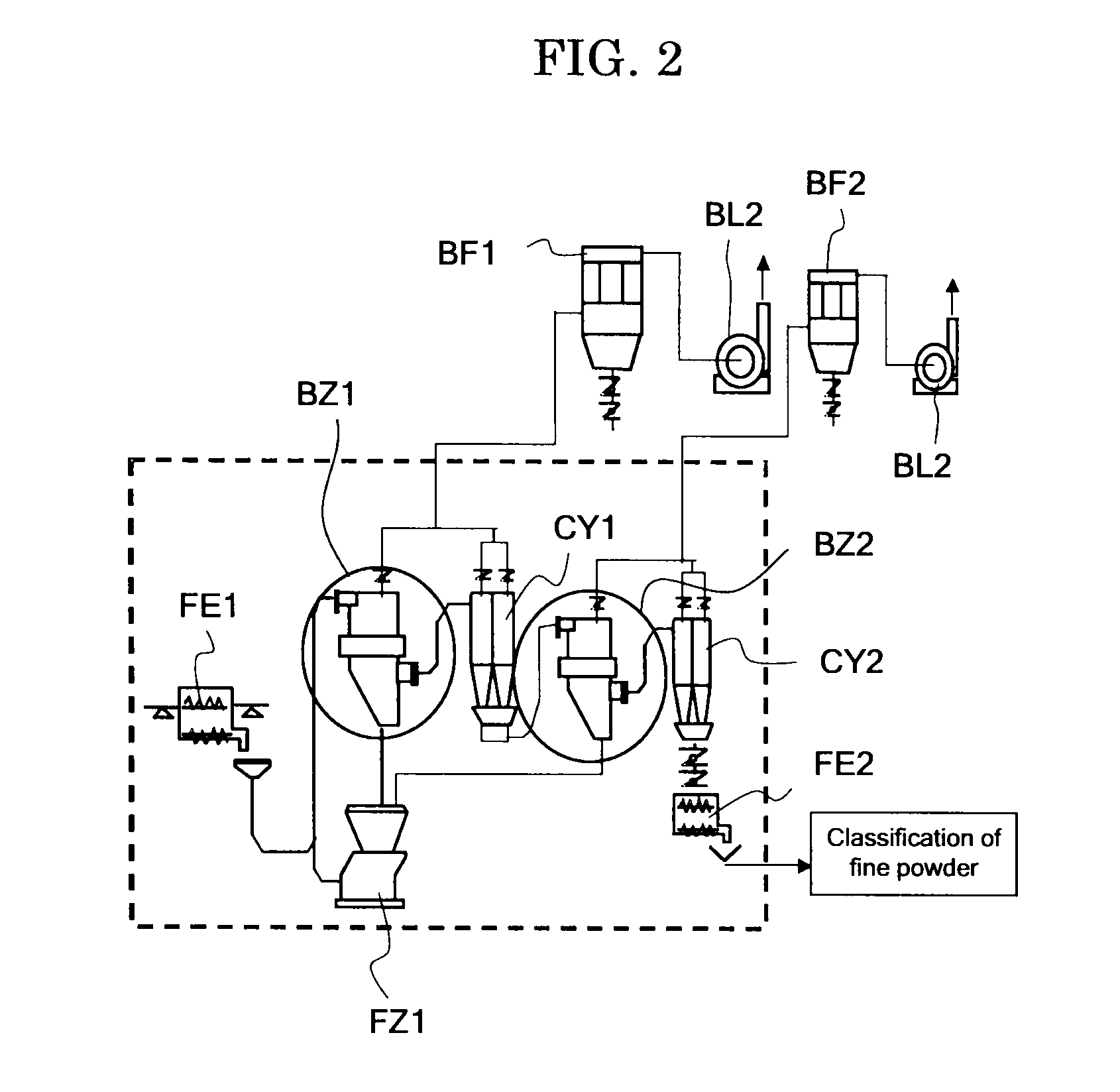
[0059]In this example, the number N of the guide slats 1q of the louver ring 1Q of the classifier BZ1 was changed to R / 15 (where R was the length (in mm) of the inner periphery of the casing of the dispersion chamber)). Other than that, the same classification flow of coarsely pulverized powder as described in Example 1 was carried out using the same air classifier BZ1 having the construction shown in FIGS. 5A and 5B (but with a different number of the guide slats 1q) to pulverize the same raw toner material as that used in Example 1. Feeding the raw material at a rate of 100 kg / hr yielded a toner having a particle size distribution such that a weight average particle size was 4.5 μm, a fine particle (particle diameter: 5 μm or less) content was 75POP % based on the number average and a coarse particle (particle diameter: 8 μm or greater) content of 1.0% by volume based on the weight average.

example 3

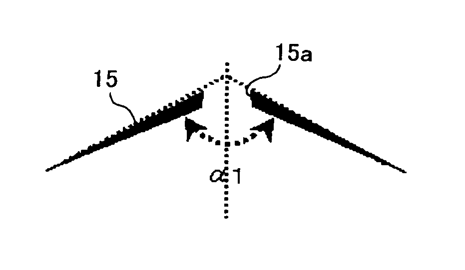
[0060]In this example, an air classifier having the construction shown in FIG. 6 was used as the air classifier BZ1 (α1=85°; the opening area A1 of the fine powder discharge port 16a=1 / 12×A2 (where A2 is the opening area of the opening 7 of the separator core 8); the fine powder discharge pipe 15b did not extend upward from the apex of the center core 15; the length L of the fine powder discharge pipe 15b=1.8×D2 (where D2 is the diameter of the opening 7 of the separator core 8); the anti-flow distortion part 14 not provided). Other than that, the same classification flow of coarsely pulverized powder as described in Example 1 was carried out to pulverize the same raw toner material as that used in Example 1. Feeding the raw material at a rate of 100 kg / hr yielded a toner having a particle size distribution such that a weight average particle size was 4.6 μm, a fine particle (particle diameter: 5 μm or less) content was 82POP % on the number average and a coarse particle (particle d...


PUM

PropertyMeasurementUnit
apex angle α1aaaaaaaaaa
distanceaaaaaaaaaa
particle diameteraaaaaaaaaa

Abstract

An air classifier contains a cylindrical casing provided with at an upper part thereof a feed port to feed high pressure air and a powder material, an umbrella-shaped center core in the casing, and an umbrella-shaped separator core arranged downstream of the center core in the casing and including an opening at center thereof. The air classifier has a configuration containing a dispersion chamber to disperse the powder material, being surrounded by an inner wall of the upper part casing and the center core, and a classification chamber to classify the powder material into fine and coarse powders by centrifugation, being surrounded by the center core, separator core and inner wall of the casing. In the dispersion chamber provided are a louver ring containing guide slats circularly arranged at regular intervals, and a space encircling the louver ring and serving as flow passage of the air and powder material.

Description

BACKGROUND OF THE INVENTION[0001]1. Field of the Invention[0002]The present invention relates to an air classifier that can effectively produce toner powder and other powder materials with sharp particle size distribution by preventing contamination with fine powder and coarse particles.[0003]2. Description of the Related Art[0004]Several traditional approaches are known for classifying (or sorting) pulverized coarse toner particles: a combination of a single classifier BZ1 and a single pulverizer FZ1 as shown in FIG. 1; a combination of two classifiers BZ1 and BZ2 and a single pulverizer FZ1 as shown in FIG. 2; and a combination of two classifiers BZ1 and BZ2 and two pulverizers FZ1 and FZ2 as shown in FIG. 3. One type of the pulverizers used in these systems is a jet pulverizer that propels raw material particles in a high pressure air stream spouted from a jet nozzle to cause the particles to collide with each other or hit a wall or other objects and thus crush (or pulverize) the...

Claims


Application Information

Patent Timeline
Patent Type & Authority Patents(United States)
IPC IPC(8): B01D21/30
CPCB07B9/02B07B7/086B07B11/02
Inventor MAKINO, NOBUYASUMASUSHIO, EIICHIMURAKAMI, FUMITOSHI
Owner RICOH KK
Features
  • R&D
  • Intellectual Property
  • Life Sciences
  • Materials
  • Tech Scout
  • Unparalleled Data Quality
  • Higher Quality Content
  • 60% Fewer Hallucinations
Learn More