Optical illuminator

a technology of optical illumination and diffuser, which is applied in the direction of electric lighting with batteries, semiconductor lasers, lighting and heating apparatus, etc., can solve the problems of high assembly cost, complex current technology of packaging vcsels, and inability to provide detailed descriptions of how the diffuser is attached in the system, etc., to facilitate airborne operation of portable illuminator, wide angle illumination, and small form factor portability

Active Publication Date: 2014-03-18
PRINCETON OPTRONICS
View PDF16 Cites 123 Cited by
  • Summary
  • Abstract
  • Description
  • Claims
  • Application Information

AI Technical Summary

Benefits of technology

[0016]One aspect of the invention is to provide an electrical contact from the emitter side to the non-emitter side of the array chip, such that both the terminals of the array chip are accessible on the same side of the module, thereby providing surface mounting capability. Advantageously, an optical module constructed according to this invention eliminates the need for wire or ribbon bonding, and / or via holes through the substrate.
[0021]In a different embodiment, an optical illuminator comprising one or more VCSEL array modules is provided. The optical illuminator may be configured as a surface mountable module or as a stand-alone illuminator by integrating electronic circuit(s) with the illuminator module on a common printed circuit board (PCB). The electronic circuit(s) provides operation and control functions, such as drive current and / or logic control, signal detection, etc. to the illuminator. The array module and the electronic circuit(s) are adapted for surface mounting. Electrical connection between the array module and one or more electronic circuit(s) may be provided on a common level of the PCB, or on multiple levels of a multi-level PCB. Advantageously, the illuminator modules provided in this invention may be expanded in a modular fashion to increase the surface area and / or optical power output.
[0025]In another embodiment a portable illuminator is provided. The VCSEL array chips are provided on a water cooled surface of a three dimensional structure, for example a hemispherical object, to provide a wide angle illumination of a scene. Advantageously, the small form factor portability and capability facilitates airborne operation of the portable illuminator in certain scene illumination applications.

Problems solved by technology

Current technology for packaging VCSELs is quite complex.
However, no detailed description is provided about how the diffuser is attached in the system especially since the diffuser has to be vibrated to eliminate speckle effects.
For larger arrays having many emitting devices the assembly procedure becomes very expensive.

Method used


Image

  • Optical illuminator
  • Optical illuminator
  • Optical illuminator

Examples


Embodiment Construction

[0050]Various aspects of this invention representing a broad framework of the principles will be described using exemplary embodiments and represented in different drawing figures. For clarity and ease of description, each embodiment includes only a few aspects. However, different aspects presented in each embodiment may be practiced separately or in various combinations. Many different combinations and sub-combinations of the representative embodiments within the broad framework presented in this written specification, may be apparent to those skilled in the art but not explicitly shown or described, should not be construed as precluded.

VCSEL Array Chip

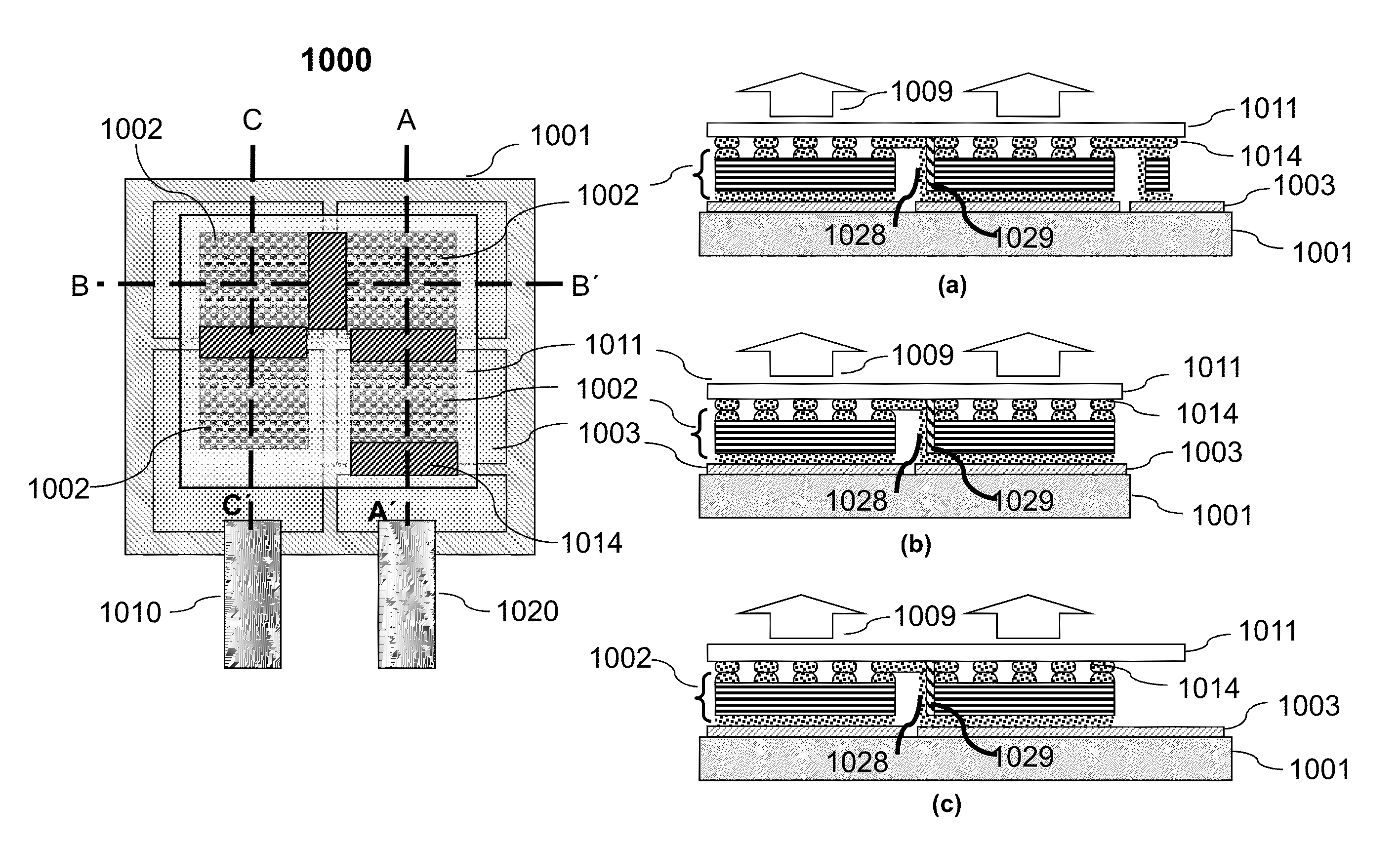
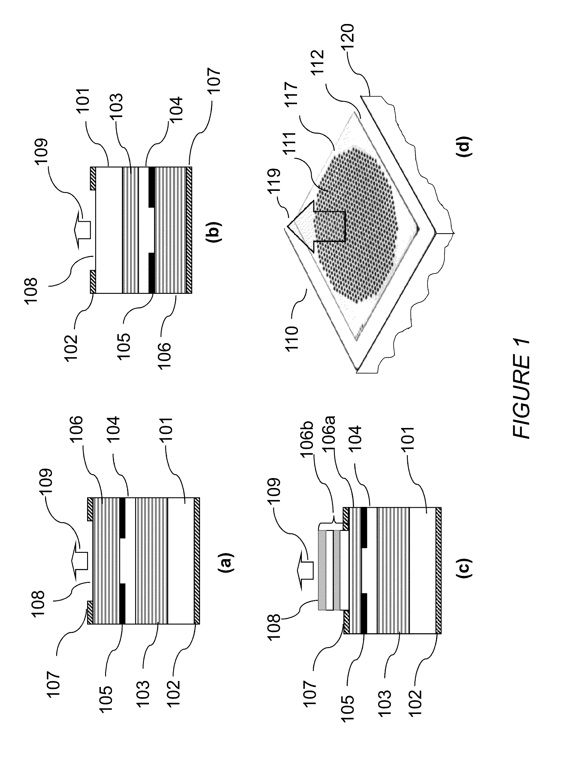
[0051]Referring now to FIG. 1, there it shows several individual VCSEL devices and a VCSEL array constructed of VCSEL devices that are used in configuring optical illuminators to be described in detail. For clarity and ease of description, only basic two terminal VCSEL devices emitting in a direction perpendicular to plane of the sub...


PUM


Abstract

Illuminator module comprising VCSEL arrays with planar electrical contacts, readily adaptable for surface mounting, is provided. Monolithic VCSEL arrays are configured in array patterns on two and three-dimensional surfaces. Illuminator modules are easily expandable by increasing the array size or by modularly arranging more arrays with or without a transparent substrate. Different shapes of illuminator modules may be configured by tiling array modules monolithically on a common substrate, or by tiling small modules. The surface mountable illuminator modules are easily assembled on a thermally conductive surface that may be air or liquid cooled for efficient heat dissipation. Array modules may be integrated with other electronic circuits such as current drivers, sensors, controllers, processors, etc. on a common platform, for example, a single or multiple layer printed circuit boards (PCB) to assemble illumination systems for different applications including a gesture recognition apparatus and a battery operated portable illuminator devices.

Description

CROSS REFERENCE TO RELATED APPLICATION[0001]This application is a Continuation-In-Part of the U.S. patent application Ser. No. 13 / 337,098 filed on Dec. 24, 2011, and Continuation-In-Part of the U.S. patent application Ser. No. 13 / 369,581 filed on Feb. 9, 2012; the disclosures of the above mentioned applications are being incorporated by reference in their entirety.BACKGROUND OF THE INVENTION[0002]1. Field of the Invention[0003]The present invention relates to optical illumination systems and in particular to optical illuminator configured from arrays of Vertical Cavity Surface Emitting Lasers (VCSEL).[0004]2. Related Background Art[0005]Optical illumination is widely used in a large number of applications whether applied to reflect incident optical radiation, such as optical imaging, or medical imaging, etc. or applied to absorb incident radiation, such as optical pumping of a gain medium in a solid state laser. New and more efficient optical sources are emerging that may be suitabl...

Claims


Application Information

Patent Timeline
Patent Type & Authority Patents(United States)
IPC IPC(8): H01S3/097H01S5/42
CPCH01S5/141H01S5/18305H01L2224/48091H01S5/02469F21V29/022F21V29/22H01S5/02276H01S5/005H01S5/423F21L4/02H01S5/02248H01L2224/48137H01S5/18308H01S5/02476F21V29/30H01S5/02272F21V29/65F21V29/70H01S5/4018H01S5/02325H01S5/02345H01S5/0237H01L2924/00014F21V29/67F21V29/56F21V29/74
Inventor SEURIN, JEAN FGHOSH, CHUNI LWANG, QINGWATKINS, LAURENCE
Owner PRINCETON OPTRONICS
Why Eureka
Try Eureka