Air conditioner for vehicle

a technology for air conditioners and vehicles, applied in vehicle position/course/altitude control, process and machine control, instruments, etc., can solve the problems of difficult to improve fuel efficiency in comparison examples, and achieve the effect of reducing fuel consumption, reducing waste heat of engines absorbed by engine coolant, and improving engine operation efficiency

Inactive Publication Date: 2014-04-01
DENSO CORP
View PDF13 Cites 8 Cited by
  • Summary
  • Abstract
  • Description
  • Claims
  • Application Information

AI Technical Summary

Benefits of technology

[0008]Moreover, the vehicle air conditioner described in Patent Document 3 adjusts a flow amount of engine coolant flowing through the heater core such that a temperature of the engine coolant, which flows out of the heater core into the engine, is made to be higher than a predetermined temperature. Thus, a temperature of the engine is prevented from reducing. As a result, when heating operation of the vehicle compartment is performed in a stop state of the engine, frequency of restart of the engine for its warm-up is reduced. Therefore, fuel efficiency of the vehicle in the stop state of the engine is improved.
[0009]It can be considered that the fuel efficiency of the vehicle may be further improved, if an operational efficiency of the engine according to Patent Document 3 is improved by using the power controller of Patent Document 2 as in a comparison example shown in FIG. 6. However, according to a study of the present applicant, it may be difficult to improve the fuel efficiency in the comparison example.
[0011]As shown by an arrow α in FIG. 5, when the operational efficiency of the engine is improved from the state of the bar graph (a) to the state of the bar graph (b), the fuel consumption can be reduced without changing actual work of the engine. At the same time, waste heat of the engine absorbed by engine coolant decreases as shown by an arrow β in FIG. 5. Thus, a temperature of the engine coolant flowing into a heater core decreases.
[0012]Subsequently, in order to perform the heating operation of the vehicle compartment appropriately, a heating capacity of a heat pump cycle is required to increase, and thus an electric power supplied to a compressor of the heat pump cycle is required to be improved. Hence, the actual work of the engine has to be increased as shown by an arrow γ in FIG. 5. As a result, in the heating operation shown in the bar graph (c) of FIG. 5, the total fuel consumption of the engine is increased as shown by an arrow δ in FIG. 5 as compared with the non-heating operation, and the fuel efficiency thereby decreases.
[0017]As shown in FIG. 6, when the operational efficiency of the engine is improved as in the comparison operation state, the temperature of the engine coolant in a driving state of the engine is difficult to be increased to a highest value in the general operation state. Hence, when the engine stops and the flow amount of the engine coolant flowing through the heater core is reduced in the comparison operation state, the first heat amount hm1 becomes almost zero, and the second heat amount hm2 is required to more increase. However, if the second heat amount hm2 is more increased, the COP of the heat pump cycle is reduced substantially.
[0018]Moreover, because the heat pump cycle consumes electrical power in the COP-decreased state, the actual work of the engine is required to be more increased for generating electricity used for compensating the consumed electrical power at the next time of activation of the engine. Therefore, the fuel efficiency further decreases.

Problems solved by technology

However, according to a study of the present applicant, it may be difficult to improve the fuel efficiency in the comparison example.

Method used


Image

  • Air conditioner for vehicle
  • Air conditioner for vehicle
  • Air conditioner for vehicle

Examples


embodiments

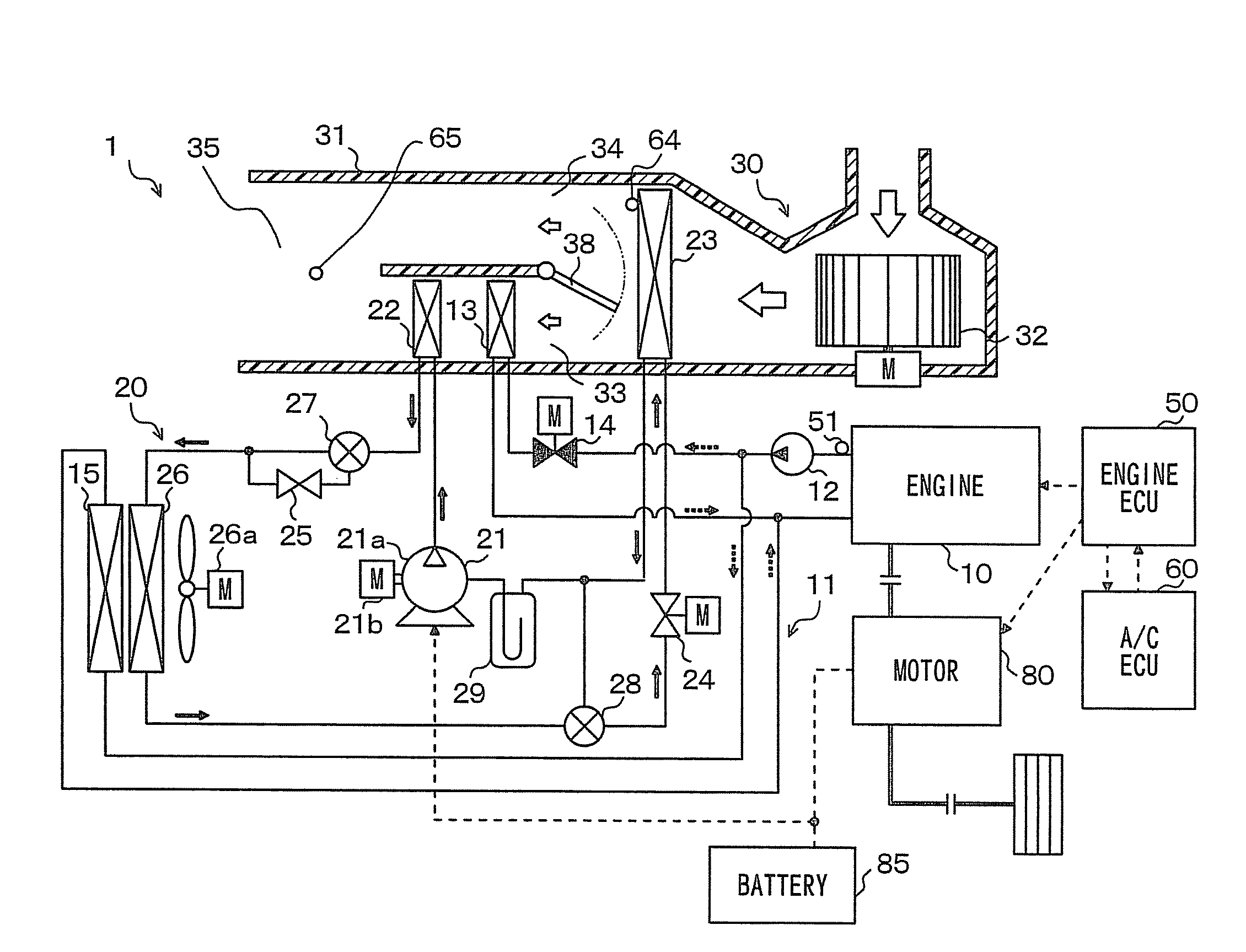
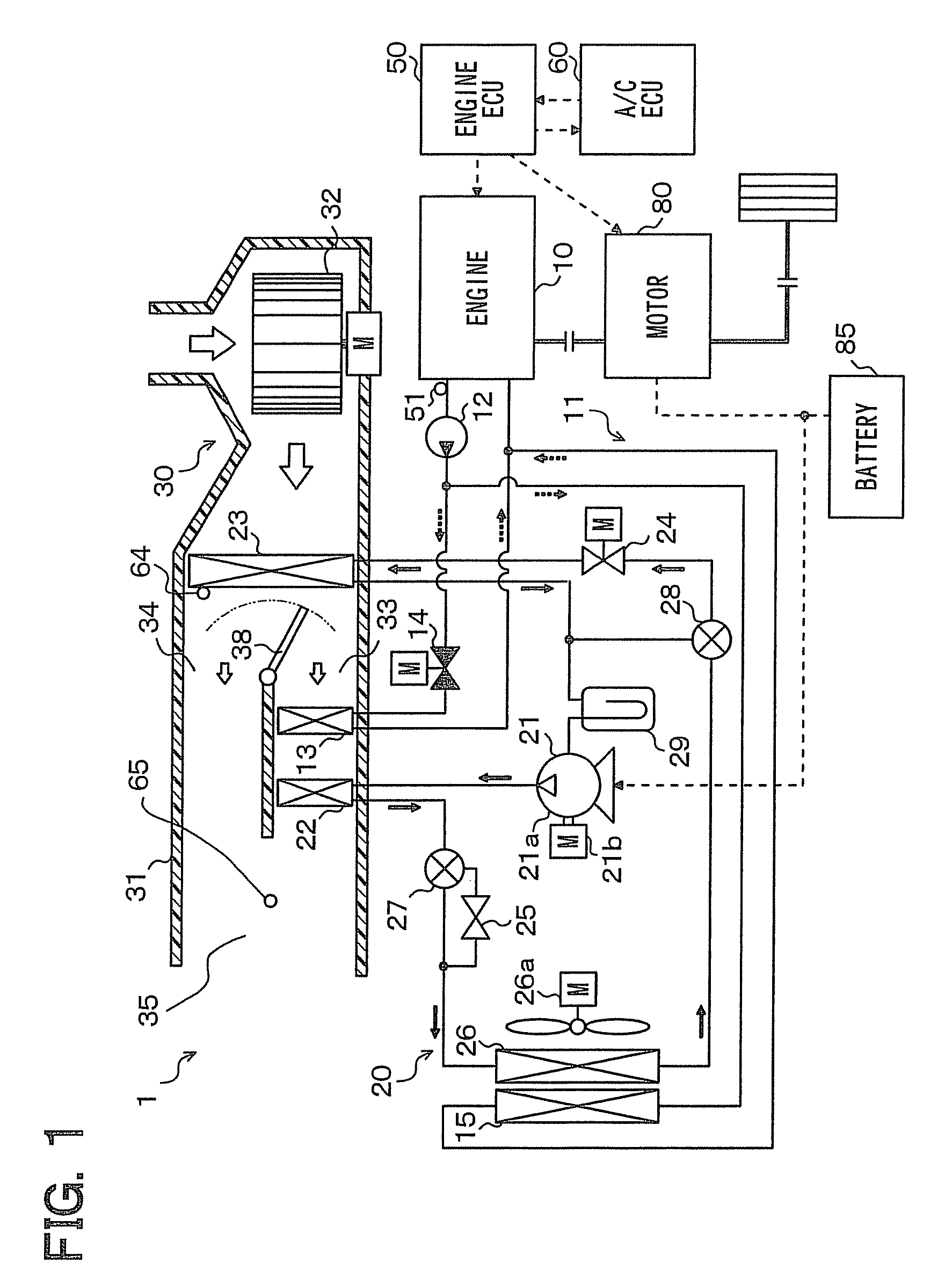
[0027]An exemplar embodiment of the present disclosure will be described hereinafter referring to FIGS. 1 to 4. In the present exemplar embodiment, an air conditioner 1 for a vehicle is typically used for a hybrid vehicle (HV) in which a driving power for running is obtained from an internal combustion engine 10 and an electrical motor 80.

[0028]The hybrid vehicle in the present exemplar embodiment can generally switch its running states by actuating or stopping the engine 10 depending on a running load of the vehicle. For example, in one (hybrid vehicle state) of the running states, driving power is obtained from both of the engine 10 and the electrical motor 80. In another state (electric vehicle state), driving force is obtained only from the electrical motor 80 by stopping the engine 10. Accordingly, the hybrid vehicle can improve its fuel efficiency as compared to a vehicle in which driving power is obtained only from an engine.

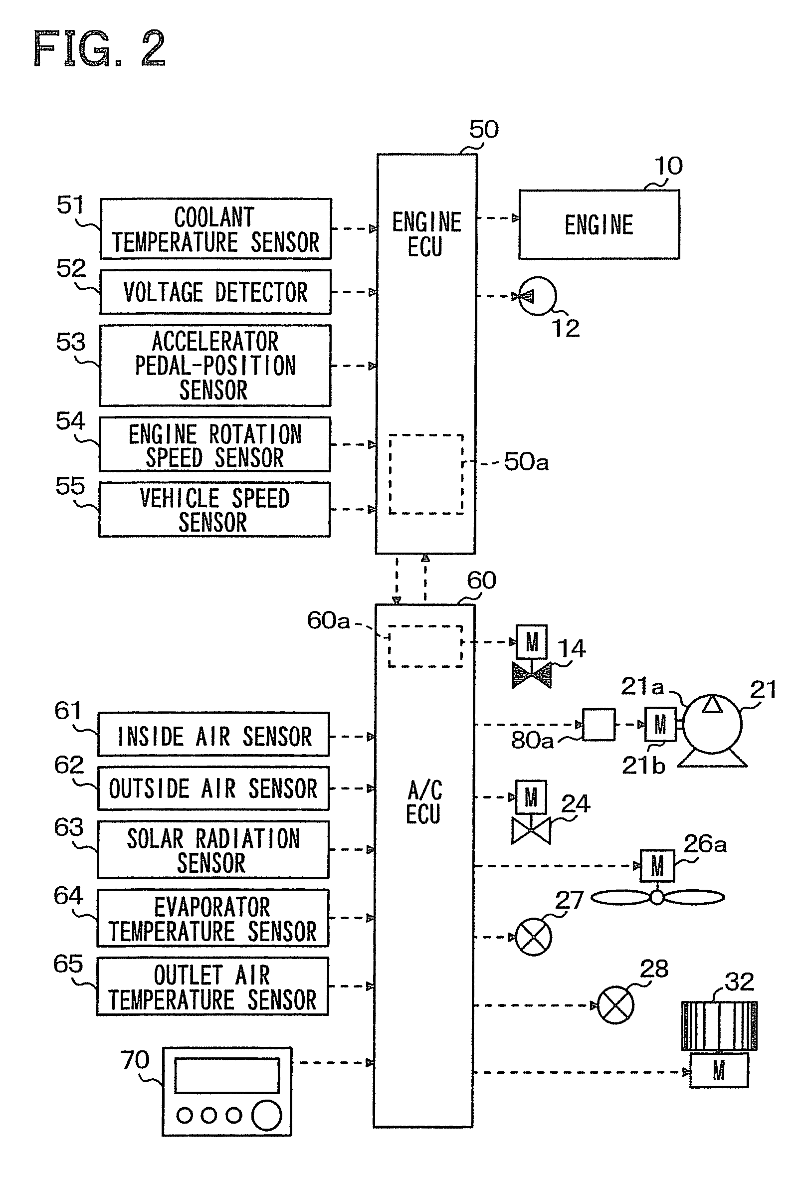
[0029]The engine 10 is a gasoline engine controlled...


PUM


Abstract

An air conditioner for a vehicle in which an operational efficiency of an in-vehicle equipment is controlled, includes a first heating portion which heats air to be blown into a vehicle compartment by using heat medium, a second heating portion which heats the blown air by using heating energy outputted from the in-vehicle equipment, a determination portion which determines a target heat amount ratio that is a target value of a heating amount ratio of a second heat amount used in the second heating portion to a first heat amount used in the first heating portion, and a heating adjustment portion which adjusts at least one of the first and second heat amounts such that the heat amount ratio approaches the target heat amount ratio. The target heat amount ratio is increased in accordance with an increase of the operational efficiency.

Description

CROSS REFERENCE TO RELATED APPLICATION[0001]This application is based on and incorporates herein by reference Japanese Patent Application No. 2011-069538 filed on Mar. 28, 2011.TECHNICAL FIELD[0002]The present disclosure relates to an air conditioner for a vehicle, which can perform heating operation of a vehicle compartment by utilizing energy and waste heat from an equipment attached to the vehicle.BACKGROUND[0003]Conventionally, Patent Document 1 (JP2001-001749A corresponding to US 2003 / 0182955A1) describes regarding an air conditioner for a vehicle that includes an interior heat exchanger and a heater core. The interior heat exchanger is used as a condenser which condenses refrigerant in a heat pump cycle, and the heater core is a heating heat exchanger which heats air by using engine coolant (hot water) as a heat source. The engine coolant is used for cooling an engine which is an equipment attached to the vehicle. The interior heat exchanger and the heater core heat air to be ...

Claims


Application Information

Patent Timeline
Patent Type & Authority Patents(United States)
IPC IPC(8): B60H1/02B60H1/00
CPCB60H1/03B60H1/00421B60H1/3213
Inventor SHIGYO, MASAKATSU
Owner DENSO CORP
Why Eureka
Try Eureka