
Driving support apparatus of vehicle

a technology of supporting apparatus and vehicle, which is applied in the direction of steering initiation, vessel parts, instruments, etc., can solve the problems of difficult to realize the following target route by using a single steering mechanism, difficult to avoid the growth of uncomfortable feelings, and high probability of driver discomfort, so as to suppress the unstabilized vehicle behavior, detect the overriding performed by the driver, and quickly and accurately.

Active Publication Date: 2014-04-01
TOYOTA JIDOSHA KK
View PDF20 Cites 8 Cited by
  • Summary
  • Abstract
  • Description
  • Claims
  • Application Information

AI Technical Summary

Benefits of technology

This patent is about a control system for vehicles that reduces the amount of steering required to keep the car in the middle of the road during lane keeping. This is done by adjusting the angle of the steering wheel and the amount of assistance provided by the power steering system. This helps to make the car easier to control and reduces the discomfort felt by drivers when they have to steer the car a lot. The system also ensures that the vehicle doesn't change behavior in an unnatural way when the driver tries to steer it. This control system is useful for improving the overall performance and safety of vehicles.

Problems solved by technology

Moreover, in the configuration that the rudder angle can be changed by applying to the steering system an assist torque for assisting the steering torque given by the driver, the steering wheel is operated independently of the driver's will, and thus the driver can highly likely feel uncomfortable.
In other words, it is generally hard to realize the following for the target route by using a single steering mechanism, while suppressing the driver's uncomfortable feeling.
Thus, if it is tried to realize the target rudder angle based on the curvature radius by using the electrically-assisted power steering apparatus, it is hardly possible to avoid the growth of the uncomfortable feeling.
Also in cases where it is tried to control the deviation of the yaw angle and the lateral position by using the steering angle varying apparatus, if the driver does not fix the steering wheel (i.e. if the driver does not firmly hold it), the steering wheel is turned due to a road surface reaction force and it is hardly possible to make the vehicle follow the target route.

Method used


Image

  • Driving support apparatus of vehicle
  • Driving support apparatus of vehicle
  • Driving support apparatus of vehicle

Examples


first embodiment

Structure of Embodiment

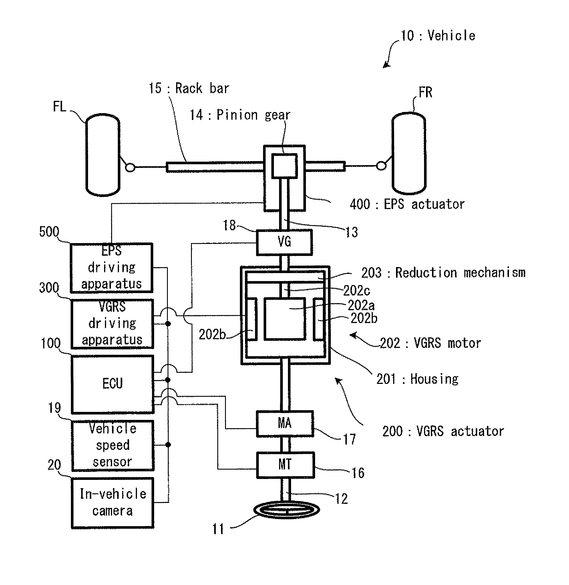
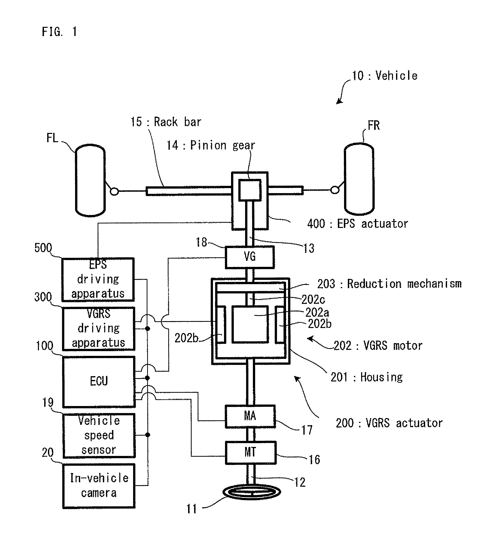
[0056]Firstly, with reference to FIG. 1, the structure of a vehicle 10 in the embodiment will be explained. FIG. 1 is a schematic configuration diagram conceptually showing the structure of the vehicle 10.

[0057]In FIG. 1, the vehicle 10 is provided with a pair of front wheels FL and FR on either sides as steered wheels, and it is configured to move in a desired direction by steering the front wheels. The vehicle 10 is provided with an ECU 100, a VGRS actuator 200, a VGRS driving apparatus 300, an EPS actuator 400 and an EPS driving apparatus 500.

[0058]The ECU 100 is provided with a CPU (Central Processing Unit), a ROM (Read Only Memory) and a RAM (Random Access Memory), each of which is not illustrated, and it is an electronic control unit capable of controlling all the operations of the vehicle 10. The ECU 100 is one example of the “driving support apparatus of the vehicle” of the present invention. The ECU 100 is configured to perform each of LKA control, EP...

embodiment

Operations in Embodiment

[0079]Hereinafter, with reference to the drawings as occasion demands, the operations in the embodiment will be explained.

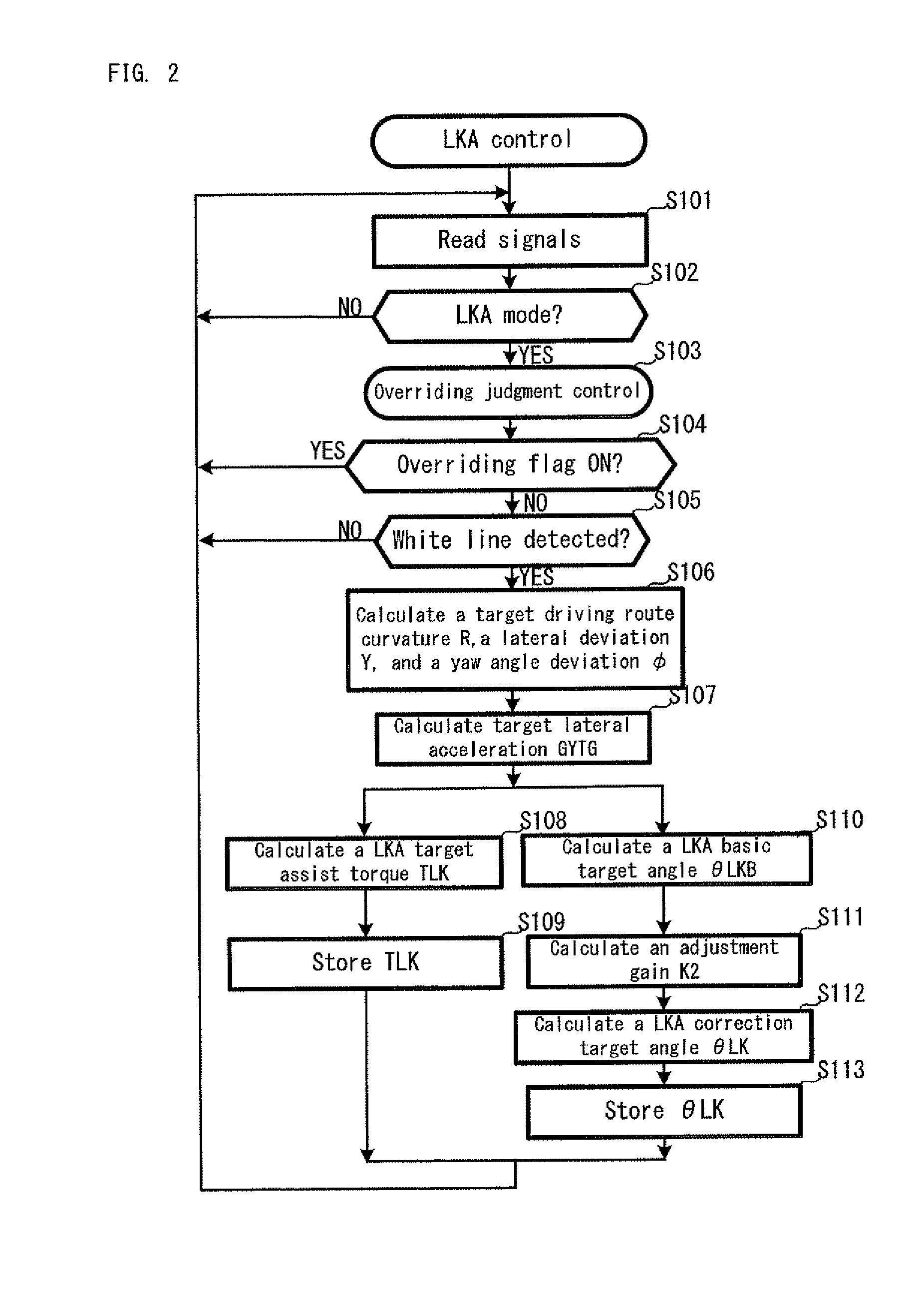
[0080]Firstly, with reference to 2, an explanation will be given on the details of the LKA control performed by the ECU 100. FIG. 2 is a flowchart showing the LKA control. Incidentally, the LKA control is control for making the vehicle 10 follow a target driving route (lane) and for realizing one portion of a driving support system owned by the vehicle 10.

[0081]In FIG. 2, the ECU 100 reads various signals including sensor signals associated with the aforementioned various sensors, various flags, and operation signals for operating various switches and the like provided for the vehicle 10 (step S101) and judges whether or not a LKA mode is selected as a result of the driver operating an operation button for initiating the LKA control disposed in the vehicle interior of the vehicle 10 in advance (step S102). If the LKA mode is not selected (...

second embodiment

[0130]Next, a second embodiment will be explained. In the second embodiment, in performing the overriding judgment, as opposed to the aforementioned first embodiment, it is judged by the judging device whether or not the overriding takes place, on the basis of the specified steering torque and threshold value.

[0131]Incidentally, the second embodiment is the same as the first embodiment except in the overriding judgment control; namely, the second embodiment is the same as the first embodiment in the EPS control, the VGRS control and the like. Therefore, here, an explanation will be given on the overriding judgment control which is different from that in the first embodiment, and an explanation will be omitted on the other controls which are the same as those in the first embodiment.

[0132]With reference to FIG. 11 and FIG. 12, an explanation will be given on the overriding judgment control in the second embodiment. FIG. 11 is a flowchart showing the overriding judgment control in the...


PUM


Abstract

A driving support apparatus of a vehicle supports driving of the vehicle, the vehicle includes a rudder angle varying device capable of changing a relative relation between a steering angle and a rudder angle. The driving support apparatus includes a following control device for controlling the rudder angle varying device such that the vehicle follows a target driving route; a steering angle specifying device for specifying the steering angle; and a judging device for judging whether or not overriding performed by a driver takes place on the basis of the specified steering angle and a reference steering angle which is the steering angle in making the vehicle follow the target driving route. The following control device stops the vehicle following for the target driving route if it is judged that the overriding takes place.

Description

TECHNICAL FIELD[0001]The present invention relates to a driving support apparatus, such as LKA (Lane Keeping Assist), in a vehicle provided with various steering mechanisms, such as EPS (Electronic controlled Power Steering) or VGRS (Variable Gear Ratio Steering).[0002]As this type of apparatus, there has been suggested an apparatus for enabling lane keeping driving by using a steering angle varying apparatus and an electrically-assisted power steering apparatus (e.g. refer to a patent document 1). According to the steering control apparatus of a vehicle disclosed in the patent document 1 (hereinafter referred to a “conventional technology”), the vehicle can be driven well along a target driving route by controlling the electrically-assisted power steering apparatus to obtain a target rudder angle based on a curvature radius at the time of lane keeping driving and by controlling the deviation of a yaw angle and the lateral position of the vehicle with respect to a driving route.[000...

Claims


Application Information

Patent Timeline
Patent Type & Authority Patents(United States)
IPC IPC(8): B62D12/00G06F17/00A01B69/00B62D11/00G06F7/00B63H25/04B62D6/00B63G8/20G05D1/00
CPCB62D15/025B62D5/008B62D1/286
Inventor LIMPIBUNTERNG, THEERAWATKOJO, TAKAHIRONITTA, HIROFUMIASAI, SHOJI
Owner TOYOTA JIDOSHA KK
Learn More