Compact electronic reverberation chamber

a compact electronic and chamber technology, applied in the direction of resistance/reactionance/impedence, relays, instruments, etc., can solve the problems that the overall emc/emi property of the dut cannot be evaluated entirely in a fixed polarization test, experience faulty performance, etc., to facilitate the dynamic three-dimensional (3d) manipulation of em field polarization, uniform field distribution, fine control of field polarization

Active Publication Date: 2014-04-08
THE UNIVERSITY OF HONG KONG
View PDF7 Cites 6 Cited by
  • Summary
  • Abstract
  • Description
  • Claims
  • Application Information

AI Technical Summary

Benefits of technology

[0008]The preset invention is also directed to an improved reverberation chamber which facilitates the dynamic three dimensional (3D) manipulation of EM field polarization and produces a uniform field distribution inside the compact reverberation chamber. This improved reverberation chamber enables the fine control of field polarizations by altering the state of the tunable surfaces of the chamber without the need to rotate the DUT for different polarized wave illuminations.

Problems solved by technology

Certain commonly-used electronic devices, such as cell phones, laptops or portable media players, as a few examples, may be immersed in a multipath environment in actual use and may, for example, experience faulty performance as a result of interference from various electromagnetic fields.
Nevertheless, the overall EMC / EMI property of the DUT cannot be evaluated entirely in a test with a fixed polarization.

Method used


Image

  • Compact electronic reverberation chamber
  • Compact electronic reverberation chamber
  • Compact electronic reverberation chamber

Examples


embodiment 500

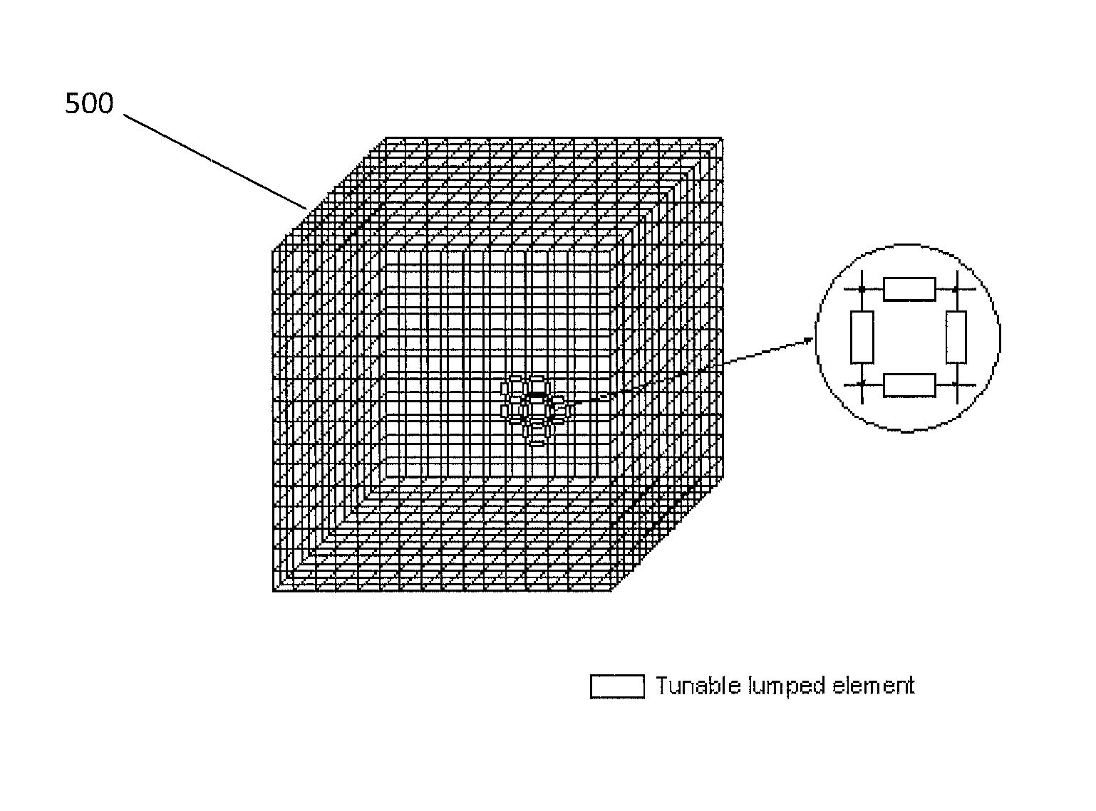
[0041]As illustrated in FIG. 5, the electronic reverberation chamber device 500 of the present invention includes a Faraday cage of wire mesh. The electronic reverberation chamber 500, in this embodiment, can function similarly to a metal-mesh-screened window in the front of a microwave oven, which effectively keeps microwaves with a certain wavelength inside the chamber from escaping to an outside environment. In this particular embodiment, electromagnetic energy under a certain frequency range is trapped inside a wire mesh cage. However, a wire mesh structure may also effectively shield an interior of an electronic reverberation chamber embodiment 500 from external electromagnetic radiation if the mesh wires are thick enough and the holes are much smaller than a radiation wavelength. Furthermore, wire meshes may include lumped elements, such as varactor diodes, which may be electronically tuned. A variation of tunable lumped elements may alter or affect a surface impedance of a wi...

exemplary embodiment 600

[0042]FIG. 6 illustrates an exemplary embodiment 600 of a unit cell that is realized by a complementary square loop resonator. FIGS. 4 and 6 both illustrate slightly altered views of similar embodiments where metal material (405, 605) are placed or formed on top of another substance 410 and 610, such as a dielectric, a polymer or other insulating material. In the illustrated embodiment, a layer of metal is also placed on an opposing side of substances 410 and 610. Thus, substances 410 and 610 may be sandwiched between two metal layers. An embodiment of the illustrated device allows for the depicted structure to be realized by employing a printed circuit board (PCB) technique. A metal cross as shown in FIG. 4 may include tunable lumped elements 415, as explained in more detail below. Likewise, as illustrated in FIG. 6, tunable lumped elements 615 may be located on a square loop gap.

[0043]In one arrangement of elements of the present device, varactor diodes are utilized as tunable lum...

embodiment 700

[0048]FIGS. 7 and 8 illustrate perspective and top views, respectively, of an embodiment 700 of a phase shifting wall comprising a wire mesh 705 with varactor diodes 710 on a printed circuit board 715. In a particular embodiment of the present invention an electromagnetic wave impinging upon phase shifting wall 700 will induce electric currents to flow within wire mesh 705. An electric charge then flows around a path through wire mesh 705, varactor diodes 710, and via a metal plate located on the bottom of printed circuit board 715. Varactor diodes may have a variable capacitance that may be generally a function of a voltage applied across their terminals. In some implementations, of course, tunable lumped elements other than varactor diodes 710 may be used, such as discussed below, for example.

[0049]FIG. 9 illustrates an element of the present invention incorporating a parallel resonant LC circuit 900. The parallel resonant LC circuit 900 may be used to approximate a phase shifter ...


PUM


Abstract

A method and apparatus provide an improved EM reverberation chamber which facilitates the dynamic three dimensional (3D) manipulation of EM field polarization within the chamber and produces a uniform field distribution inside the chamber. The chamber includes one or more walls with tunable lumped elements. A controller is provided to generate one or more control signals that are applied to the lumped elements and tunes their impedance in response to the one or more control signals. The result is to generate, within the chamber an electromagnetic field that appears to be random or pseudo-random in polarization, but which is sufficiently uniform in magnitude for EM testing.

Description

[0001]The present application claims the benefit of priority from Provisional Patent Application No. 61 / 433,816 filed Jan. 18, 2011, which is incorporated herein by reference.FIELD OF THE INVENTION[0002]The present invention relates to a polarization controllable electromagnetic (EM) cell which is used to generate a uniform electric field environment for the electromagnetic compatibility / electromagnetic interference or immunity (EMC / EMI) testing of electronic equipment inside a reverberation chamber. In particular, the present invention is directed to a controllable electromagnetic cell that is capable of providing a wide range of electromagnetic frequencies, while at the same time requiring less electrical energy than those in the prior art.BACKGROUND OF THE INVENTION[0003]Reverberation chambers, also known as mode stirred chambers, have been viewed with increasing interest in electromagnetic (EM) related engineering research. Certain commonly-used electronic devices, such as cell ...

Claims


Application Information

Patent Timeline
Patent Type & Authority Patents(United States)
IPC IPC(8): H01H47/00G01R27/32
CPCG01R29/0821G01R29/08
Inventor CHEW, WENG CHOZHU, BOJIANG, LIJUNDAI, QI
Owner THE UNIVERSITY OF HONG KONG
Why Eureka
Try Eureka