Low temperature encapsulate welding

a technology of encapsulation and low temperature, applied in the field of load-bearing medical implants, can solve the problems of inability to use polymers for encapsulation of high density, inability to provide impermeable barriers, and degradation of leakage-sensitive circuitry, etc., to enhance the physical and performance properties of silicone, enhance the effect of thermal conductivity and substantial surface area

Active Publication Date: 2014-04-22
SMITH & NEPHEW INC
View PDF144 Cites 2 Cited by
  • Summary
  • Abstract
  • Description
  • Claims
  • Application Information

AI Technical Summary

Benefits of technology

[0014]In a refinement, the encapsulant is substantially free of thermal damage despite the close proximity of the encapsulant to the welded plate.
[0034]The encapsulant may be used in combination with a biocompatible primer to promote adhesion to the implant base metal minimizing void formation within the cavity.

Problems solved by technology

However, polymers do not provide an impermeable barrier and therefore cannot be used for encapsulation of high density, high impedance electronic circuits.
The moisture ingress will ultimately reach the electronic component resulting in electric shorting and degradation of leakage-sensitive circuitry.
In certain situations, electrical through-holes are not practical due to limited design space (e.g., <1 mm diameter) available for the parts in combination with the risk of fatigue failure of the connection due to cyclic loading of the implant.
This is difficult to achieve if the weld plate components have to be welded in close proximity with the encapsulant and the cavities are too long and narrow to allow adequate backfilling after hermetic sealing.
Given that the onset temperature of thermal degradation for these types of materials is approximately 230° C., standard welding techniques, which generate local temperatures in the 400° C.-600° C. range, are not appropriate without the risk of degradation of either mechanical or optical properties the silicone.
When exposed to high temperature conditions, the silicone will degrade leading to unpredictable performance.
Accordingly, all of these problems compromise biocompatibility and mechanical performance of the implant.
There are no existing medical grade elastomers that can meet the high temperatures (400° C.-600° C.) needed for conventional welding which is used to provide a hermetic seal in the form of a weld plate over the cavity accommodating electronic component.

Method used


Image

  • Low temperature encapsulate welding
  • Low temperature encapsulate welding
  • Low temperature encapsulate welding

Examples


Embodiment Construction

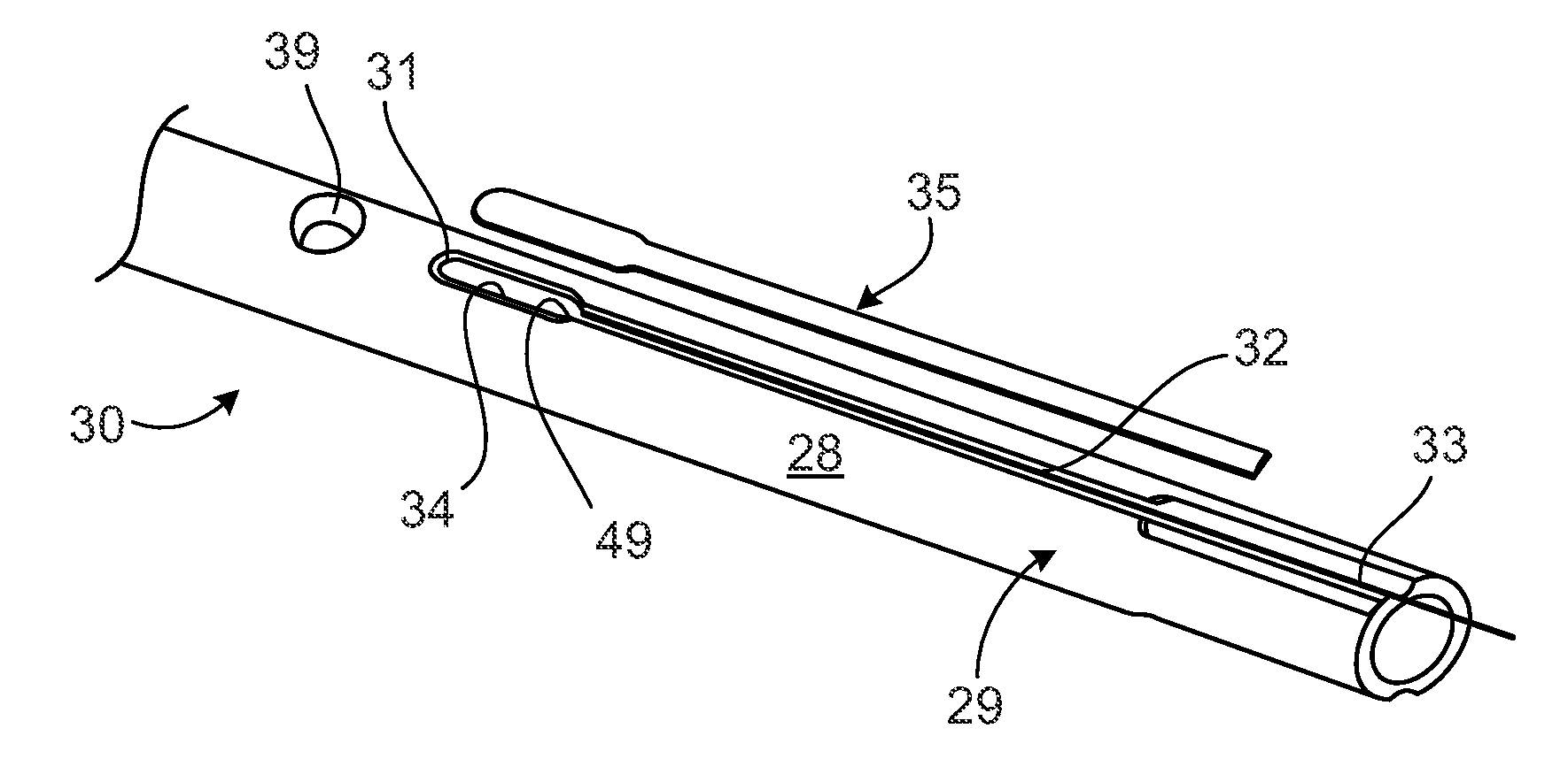
[0057]As an example, the fabrication of an IM nail 30 with an electronic component 31 and wire bus 33 is shown and described. Turning to FIG. 2, the IM nail 30 comprises a load-bearing structure in the form of a metallic (e.g., titanium) tube 29 with an outer surface 28. The outer surface 28 includes a long narrow channel 32 having a width or diameter of about 1 mm or less in the disclosed example and which may be used to house a multi-stranded wire bus 33. The wire bus 33 may extend outside of the structure of the nail 30 as shown in FIG. 2. The sensor 31 may also be designed for wireless communication and battery power thereby eliminating the need for the channel 32 and wire bus 33.

[0058]The outer surface 28 of the load bearing structure 29 also includes a larger cavity 34 for accommodating the sensor 31, which is also shown in FIG. 4. The weld plate 35 may be designed so weld lines (not shown in FIG. 2) surrounding the cavity 34 and channel 32 may be offset to ensure that the hea...


PUM

PropertyMeasurementUnit
temperatureaaaaaaaaaa
temperaturesaaaaaaaaaa
energyaaaaaaaaaa

Abstract

A load-bearing medical implant is disclosed that includes a load-bearing structure with a cavity extending into the outer surface of the structure. The cavity accommodates a sensor that is held in a fixed position within the cavity by an encapsulant. The cavity is covered by a plate that is welded over the cavity in close proximity to the sensor and encapsulant to provide a seal over the cavity and the electronic component without causing thermal damage to the encapsulant or sensor despite the close proximity of the encapsulant and sensor to the welded areas of the plate and structure. Methods for encapsulating the sensor in the cavity, methods for encapsulating a wire bus leading from the sensor through a channel in the implant and methods for pulsed laser welding of weld plate over the sensor and encapsulant with thermal damage to either are disclosed.

Description

CROSS-REFERENCE TO RELATED APPLICATIONS[0001]This application claims the benefit of U.S. Provisional Application No. 61 / 148,283, filed 29 Jan. 2009. The disclosure of this prior application is incorporated by reference in its entirety.BACKGROUND[0002]1. Technical Field[0003]This disclosure relates to various load-bearing medical implants with at least one electronic component that is sealed within a load-bearing structure of the implant to provide an impermeable barrier to protect the electronic component from body fluids. Various methods are disclosed for hermetically sealing the electronic component within a metallic load-bearing implant structure by welding a weld plate over the cavity that accommodates the electronic component without causing thermal damage to the encapsulant or electronic component. Various techniques are also disclosed for encapsulating an electronic component within a cavity of a load-bearing implant, such as an IM nail that includes one or more electronic se...

Claims


Application Information

Patent Timeline
Patent Type & Authority Patents(United States)
IPC IPC(8): B23K26/00
CPCA61B2019/461A61F2250/0001A61B2017/00526A61B17/72A61F2002/30451A61F2002/30668A61F2220/0058A61B2019/464A61B2090/064A61B2090/061Y10T29/49002
Inventor WILSON, DARREN JAMESRITCHEY, NICHOLAS S.TAYLOR, STEPHEN JAMES GUY
Owner SMITH & NEPHEW INC
Why Eureka
Try Eureka