Method for producing difluoroacetyl chloride
a technology of difluoroacetyl chloride and difluoroacetic acid, which is applied in the preparation of carboxylic compound, carboxylic compound, carbonyl compound, etc., can solve the problems of ozone destruction, inconvenient long-term production, and inaccessible raw materials such as difluoroacetic acid or derivative thereof, and achieve high selectivity and high yield
- Summary
- Abstract
- Description
- Claims
- Application Information
AI Technical Summary
Benefits of technology
Problems solved by technology
Method used
Image
Examples
reference example 1
Sensitivity Check of FID Detector
[0082]A gas chromatograph was equipped with a column according to “EPA Method 624”. On the other hand, an equivalent molar composition was prepared from samples of monofluoromethane and difluoroacetyl fluoride. The area of each component in the prepared composition was measured by the gas chromatograph. According to the measurement results, the area ratio was monofluoromethane: CHF2COF=2.41:1.00.
Raw Material Preparation Example 1
Preparation of Difluoroacetyl Fluoride
[0083]An aluminum phosphate catalyst was prepared by compression molding aluminum phosphate available from Aldrich Chemical Co. into pellets of 5 mm φ×5 mm L and firing the pellets at 700° C. for 5 hours under a nitrogen flow atmosphere. Then, a stainless steel reaction tube (inner diameter φ: 37.1 mm, length L: 500 mm) having a carburetor was packed with 200 cc of the prepared catalyst. While flowing nitrogen at 15 cc / min into the reaction tube, the reaction tube was heated externally by...
preparation example 1
Catalyst Preparation Example 1
Activation of Pd / C Catalyst
[0084]A stainless steel reaction tube having an inner diameter of 37 mm and a length of 500 mm was packed with 2% Pd / activated carbon catalyst (280 cc) available from Evonik Degussa Japan Co., Ltd. Nitrogen and hydrogen were mixed together and fed into the reaction tube at 100 cc / min and 50 cc / min, respectively, at room temperature. The reaction tube was heated so as to slowly raise the temperature of the catalyst to 350° C. over 8 hours and not to cause local heat generation in the catalyst. When the temperature of the catalyst reached 350° C., the flow rate of the hydrogen was increased by 50 cc / min every 30 minutes. The flow rate of the hydrogen was finally maintained at 518 cc / min for 8 hours. After that, the reaction tube was slowly cooled down to room temperature while only flowing the nitrogen into the reaction tube. In the above catalyst activation operation, the flow rate of the hydrogen was decreased to 10 cc / min or ...
example 4
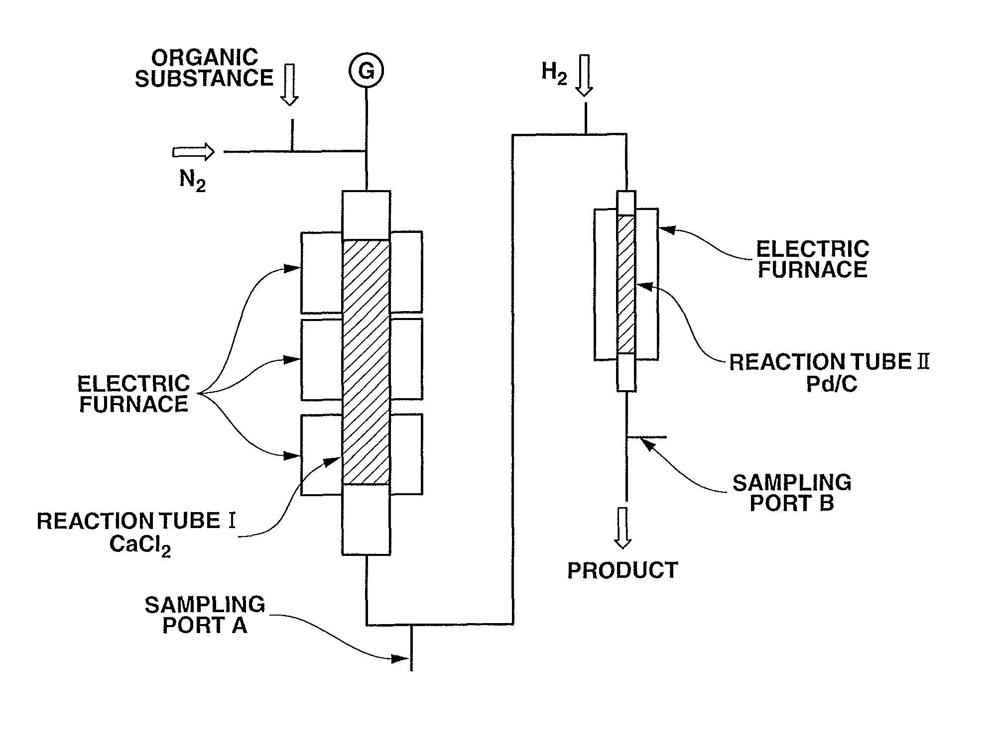
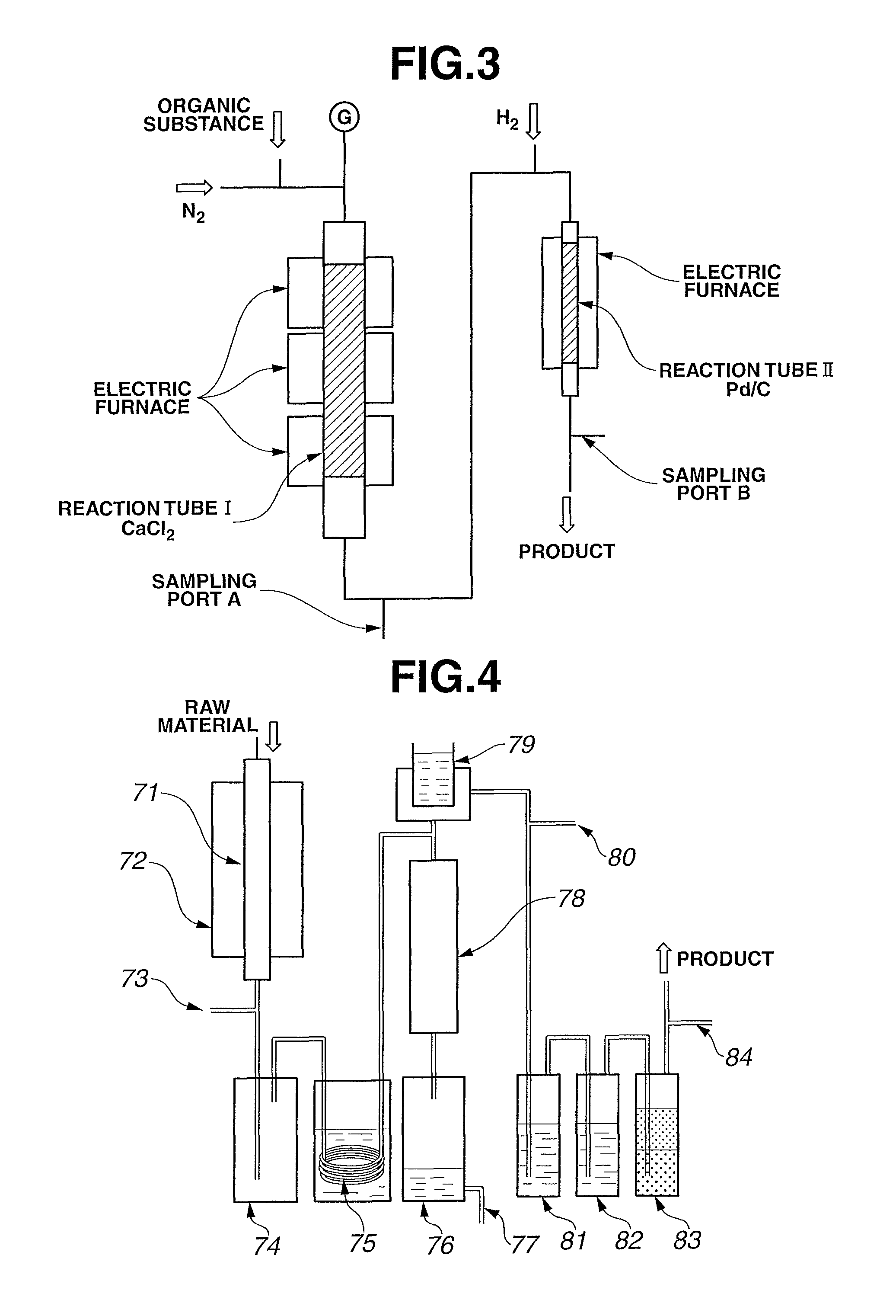
[0088]Reaction experiment was performed in the same manner as in Example 3, except for, after replacing the calcium chloride in the reaction tube I with the same amount of the same kind of fresh calcium chloride, feeding the DFAF prepared in Raw Material Preparation Example 1 as the raw material (DFAC: 99% or more, others: 1% or less). After a lapse of 140 hours, the gas product was sampled at the sampling ports A and B and analyzed by the gas chromatograph (FID). The experimental results are indicated in TABLE 1.
PUM
| Property | Measurement | Unit |
|---|---|---|
| temperature | aaaaa | aaaaa |
| temperature | aaaaa | aaaaa |
| temperature | aaaaa | aaaaa |
Abstract
Description
Claims
Application Information
 - R&D
- Intellectual Property
- Life Sciences
- Materials
- Tech Scout
- Unparalleled Data Quality
- Higher Quality Content
- 60% Fewer Hallucinations
Browse by: Latest US Patents, China's latest patents, Technical Efficacy Thesaurus, Application Domain, Technology Topic, Popular Technical Reports.
© 2025 PatSnap. All rights reserved.Legal|Privacy policy|Modern Slavery Act Transparency Statement|Sitemap|About US| Contact US: help@patsnap.com


