Beam irradiation apparatus and beam irradiation control method

a beam irradiation and beam technology, applied in the field of beam irradiation control, can solve the problems of large amount of labor, large cost and time consumed in the manufacture of metal collimators, and it is difficult to shape beams with a diameter of several millimeters or less, and achieves a wide range of applications, high accuracy, and reduced damage (exposure) of normal parts.

Inactive Publication Date: 2014-05-06
GUNMA UNIVERSITY
View PDF7 Cites 0 Cited by
  • Summary
  • Abstract
  • Description
  • Claims
  • Application Information

AI Technical Summary

Benefits of technology

[0021]The present invention exhibits following effects by the configurations as described above. In the present invention, the quadrupole magnet is adopted which strongly focuses the beam in the transport pipe on the upstream side of the movable range shifter so as to enable the focusing angle of the beam to be maintained even in the vicinity of the irradiation target, and hence the beam can be shaped to have a very small diameter of several millimeters or less in the irradiation target.
[0022]Further, in the present invention, the irradiation control of the beam having the beam diameter of several millimeters or less can be highly accurately performed in about 0.1 mm increments and further 0.01 mm increments. Therefore, when the irradiation target is a human body, the beam can be irradiated onto a lesion more accurately and effectively as compared with the conventional beam irradiation therapy, and hence damage (exposure) of normal portions and a burden to the patient are reduced. When the present invention is applied to beam irradiation therapy, the beam irradiation therapy can be used for many diseases and can used in a wide application range at low cost. For example, the present invention is suitable for beam irradiation therapy of diseases, such as pituitary tumor, intravascular tumor, and age-related macular degeneration, which are difficult to be treated.
[0023]Further, in the present invention, objects, for example, an irradiation field shaping instrument, such as a metal collimator, and a ridge filter, which are installed on the beam line in order to shape an irradiation shape, are not indispensable. Therefore, it is possible to reduce the error in dose estimation due to the generation of neutrons and scattering particles which are generated at the time when the beam collides with the objects, and hence it is possible to estimate the irradiation dose with high accuracy.
[0024]Further, in the present invention, a quadrupole magnet is not needed in the very vicinity of the irradiation target for final focusing of the beam, and hence it is possible to secure the irradiation field as widely as in the case of irradiation by the conventional dispersed beam. Further, when the quadrupole magnet is not excited, the beam irradiation apparatus according to the present invention can also be operated to perform the above described conventional beam irradiation methods (1) and (2).
[0025]In addition, the present invention can be applied regardless of the types of cyclotron and synchrotron accelerators, and regardless of particle ion species, such as protons and heavy particles, and hence the present invention has high versatility.

Problems solved by technology

However, when the metal collimator is adopted, much cost and time are consumed to manufacture the metal collimator.
In addition, there is a problem that, when the broadened beam is shaped by the metal collimator, unintended radiation, such as a neutron beam, a gamma ray, and a proton beam, is generated to influence the accuracy of dose estimation.
However, for the practical use of the technique disclosed in Patent Literature 2, a large amount of labor is required because it is necessary to manage the accuracy of the power supply of the quadrupole magnet 6 and to cope with the increase in the number of excitation patterns of the quadrupole magnet 6.
Therefore, with the technique disclosed in Patent Literature 2, it is actually difficult to shape a beam having a diameter of several millimeters or less.
Until now, no technique has been known for shaping, in a target, a therapeutic beam having a diameter of about several millimeters or less without using a collimator.
Further, no method has also been known for modulating the beam spot size in the irradiation target 8 with high accuracy of, for example, 0.1 mm or less, while securing a wide irradiation field.

Method used


Image

  • Beam irradiation apparatus and beam irradiation control method
  • Beam irradiation apparatus and beam irradiation control method
  • Beam irradiation apparatus and beam irradiation control method

Examples


embodiment 1

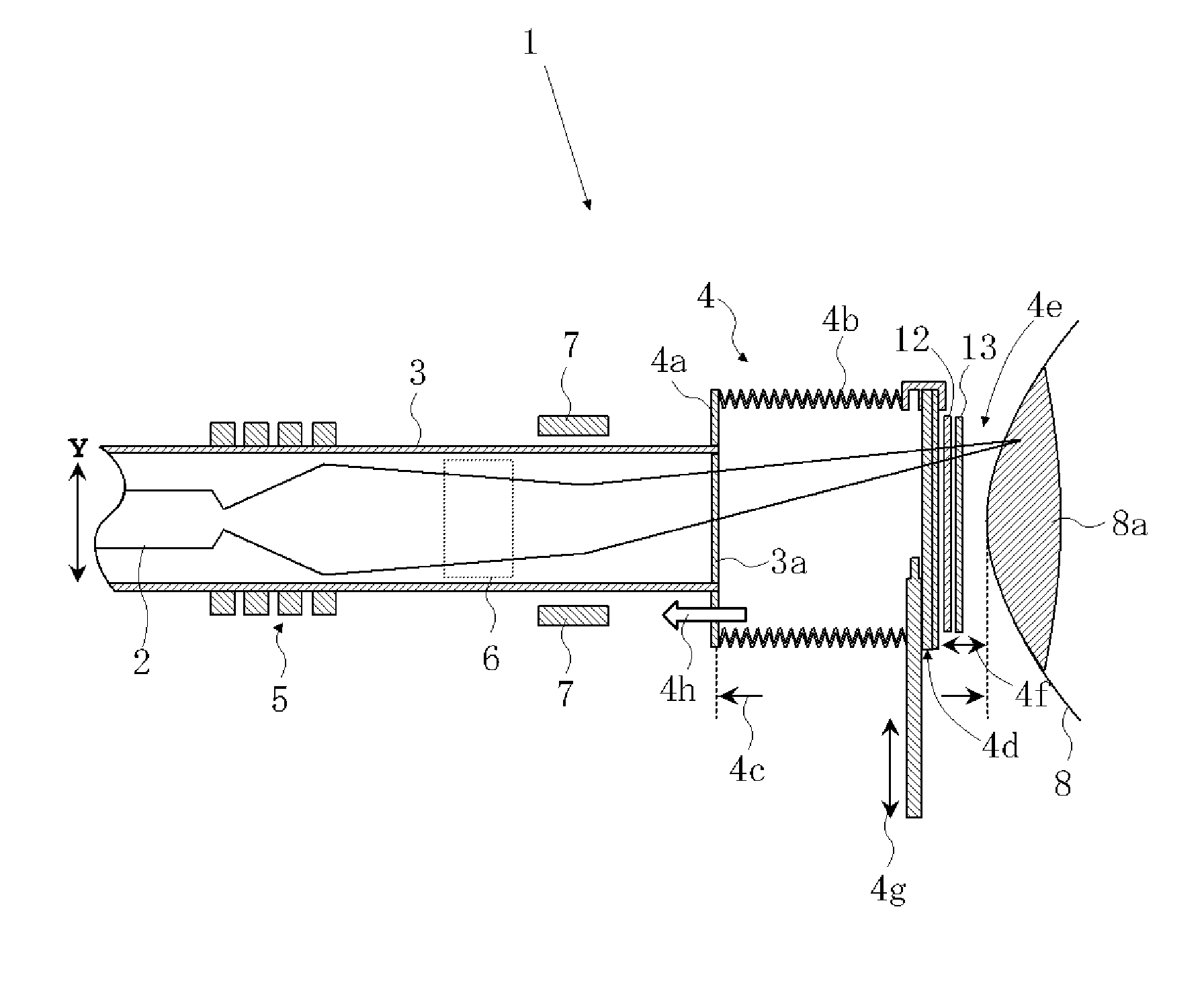
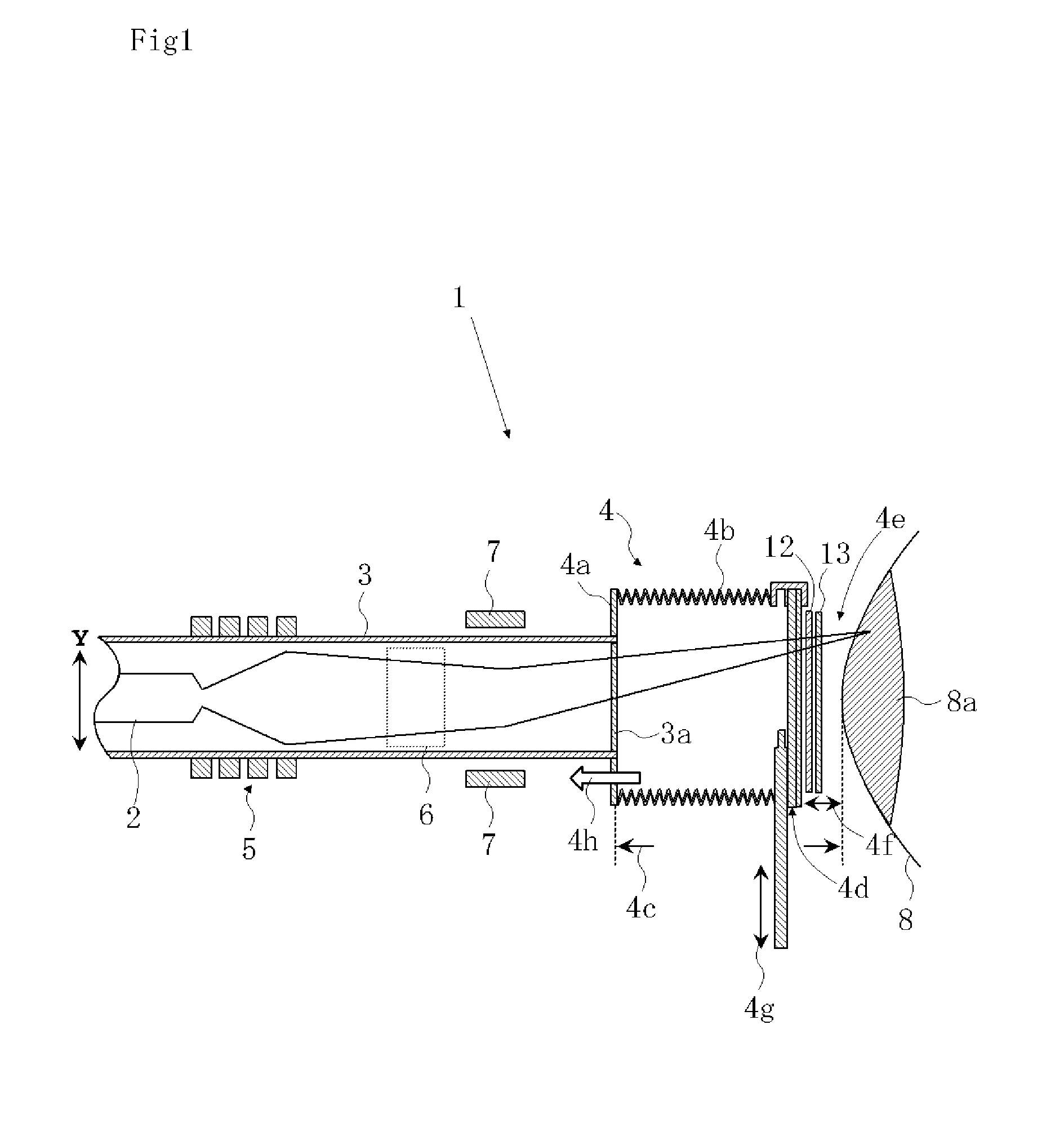
[0032]As shown in FIG. 1, a beam irradiation apparatus 1, which is one example according to the present invention, is configured by a transport pipe 3, an extraction nozzle 4 provided with a longitudinally movable range shifter 4d, a quadrupole magnet 5, and XY axis direction scanning electromagnets 6 and 7.

[0033]The transport pipe 3, which is the same as conventional one, is a hollow pipe which is connected to an accelerator and is highly evacuated, and through which a beam taken out from the accelerator passes toward an irradiation target.

[0034]The extraction nozzle 4 is configured by an extension section 4a which is extended to be continuously connected to the transport pipe 3 via a vacuum diaphragm 3a, an expanding / contracting section 4b which is connected to the extension section 4a so as to be expandable and contractible, and the movable range shifter 4d which is provided at the end portion of the expanding / contracting section 4b on the side opposite to the side of the transpo...


PUM


Abstract

The beam irradiation apparatus is featured by including a transport pipe which is vacuum-evacuated to be used as a transport channel of a beam taken out from an accelerator, a quadrupole magnet which modulates the beam diameter of the beam so that the beam is incident on an irradiation target existing in the atmosphere while maintaining the focusing angle of the beam, and one or more longitudinally movable range shifters which are provided to be capable of changing the distance to the irradiation target of the beam, and which modulate the beam range by reducing the energy of the beam by allowing the beam to pass through the movable range shifter, and is featured in that the beam is irradiated onto the irradiation target by modulating the beam diameter and the beam range.

Description

TECHNICAL FIELD[0001]The present invention relates to irradiation control of a beam. More particularly, the present invention relates to a beam irradiation apparatus which is capable of reducing, to a very small value, the diameter of a beam taken out from an accelerator and which is further capable of modulating the beam diameter, the beam range, and the beam trajectory, and also relates to a method for controlling beam irradiation, in which the range of an irradiation field in an irradiation target can be modulated with high accuracy.BACKGROUND ART[0002]In cancer therapy, heavy particle radiotherapy using heavy ions, such as carbon ions, is featured by high biological effect on tumor, high dose concentration, and low-dose exposure to normal tissue surrounding a lesion. The known heavy particle radiotherapy includes a process of confirming a treatment region on the basis of prior diagnosis using a CT, and the like, a treatment planning process in which the beam diameter, the beam r...

Claims


Application Information

Patent Timeline
Patent Type & Authority Patents(United States)
IPC IPC(8): G21K5/04
CPCA61N2005/1095A61N2005/1087G21K1/093A61N5/1043A61N5/1077
Inventor TORIKAI, KOTAYAMADA, SATORU
Owner GUNMA UNIVERSITY
Why Eureka
Try Eureka