
Piston member, an apparatus comprising the piston member, and methods and use of the piston member and the apparatus

a piston and piston body technology, applied in the direction of lighting and heating apparatus, combustion types, positive displacement liquid engines, etc., can solve the problems of high pressure reactor inert gas consumption, difficult feeding of solids into high pressure reactors, and weight loss of coal

Active Publication Date: 2014-05-13
THERMOCHEM RECOVERY INT
View PDF35 Cites 22 Cited by
  • Summary
  • Abstract
  • Description
  • Claims
  • Application Information

AI Technical Summary

Benefits of technology

The present invention provides a safer and efficient apparatus for transporting solid materials into combustible, explosive and / or poisonous atmospheres without the need for compression or direct communication between the raw material feeder and the recipient. The apparatus has high operating capacity, is easy to maintain and operational failures or stoppages are rare. The mechanical seal against the process pressure in the recipient is superior, and operating trouble can be easily remedied by replacing a component.

Problems solved by technology

Gasification relies on chemical processes at elevated temperatures greater than 700° C., which puts a high demand on safety regulations when the raw material are continuously fed to the gasifier, in particular due to presence of toxic and explosive gases.
Volatile gases are released and char is produced resulting in weight loss of coal.
The feeding of solids into a high pressure reactor has however always been difficult because of both high equipment costs and poor material characteristics.
Lock hoppers, which are the most commonly used principle for feeding against a pressure, have serious problems in the very high consumption of inert gas used for pressurizing and transfer.
Since the valves between hoppers must be operable with high concentration of solids while moved, the valves are subject to sticking and seal failure under the operating conditions.
Both the depressurizing valve and the vent lines are subject to severe abrasive conditions as the result of the rapid movement of hard solids therethrough under the influence of the differential pressure.
Such systems are thus subject to sequence control failures and unsuitable for continuous operation due to great costs.
The sealing surfaces of the apparatus described in EP 1 425 089 are very vulnerable to wear resulting in that the apparatus is prone to leak.
This means that either the apparatus can only feed into atmospheres that are not combustible, explosive or poisonous or the consumption of inert bleed gas, i.e. gas resulting from any leakage in the feeding mechanism, will be very high.

Method used


Image

  • Piston member, an apparatus comprising the piston member, and methods and use of the piston member and the apparatus
  • Piston member, an apparatus comprising the piston member, and methods and use of the piston member and the apparatus
  • Piston member, an apparatus comprising the piston member, and methods and use of the piston member and the apparatus

Examples


example

[0098]A Pilot Feeding Apparatus with Ductile Sealing Ring

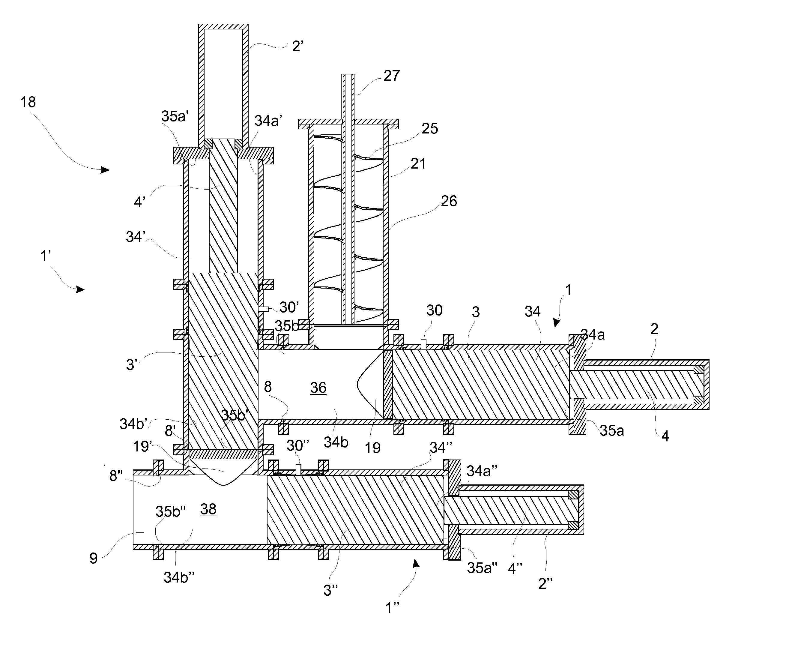
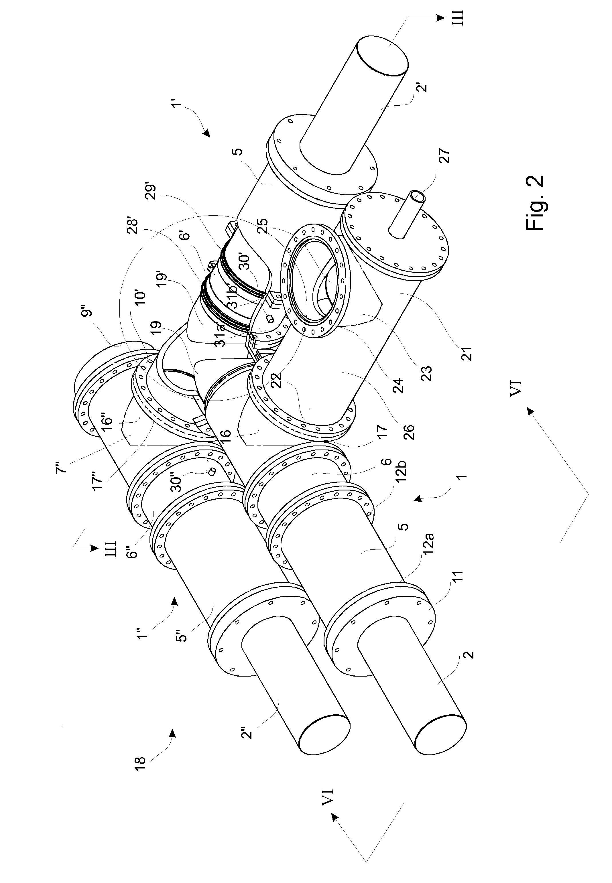
[0099]A feeding apparatus that is designed to feed coal powder having a bulk density of 650 kg pr m3 and a particle density 1300 kg / m3 against a reactor pressure of 60 bar with no gas flowing in or out of the process. A first piston member is feed axially by gravity by means of a continuous screw feeder. The first piston member co-operates with a second piston member and a third piston member all having a cylinder barrel of diameter 700 mm and a stroke length of 1000 mm.

[0100]The piston speed of the second piston member and the third piston member is 250 mm / sec. during forward transport of material and 350 mm / sec. during returning and retracting the second piston and the third piston, respectively, whereas the speed of the first piston member is 350 mm / sec during forward movement and 400 mm / sec. during returning and retracting. At the end of the forward movement of the piston members the pistons hit and deform the ductile seal...


PUM


Abstract

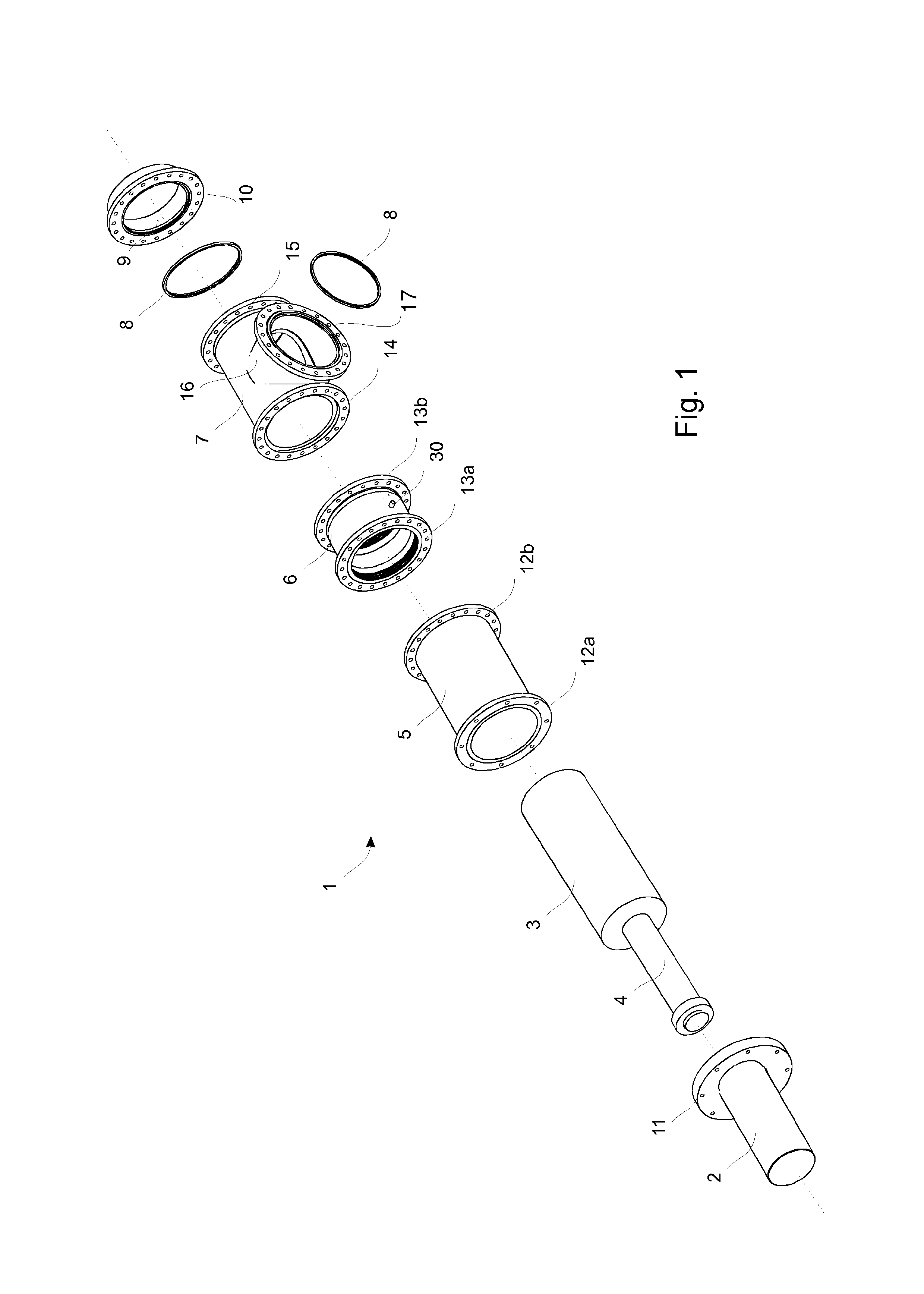
A piston member that includes a piston rod provided with a piston serves for reciprocating inside a cylinder barrel, the piston dividing the cylinder barrel chamber into a proximal cylinder barrel chamber having a proximal capped end opposite the piston and a distal cylinder barrel chamber having a distal cylinder barrel end opposite the piston. The piston member has at least one sealing ring or seat arranged inside the distal cylinder barrel chamber at the distal cylinder barrel end. Preferably three consecutive piston members are arranged to operate in a series in an apparatus for transporting coal powder to a gasifier. The movement of the pistons inside the cylinder barrels is controlled in relation to each other to transport apportioned batches of coal powder to a high pressure reactor.

Description

[0001]This application is a 371 filing of International Patent Application PCT / DK2010 / 050267 filed Oct. 13, 2010.BACKGROUND[0002]The present invention relates to a piston member comprising a piston rod provided with a piston reciprocating inside a cylinder barrel, said piston divides the cylinder barrel chamber into a proximal cylinder barrel chamber having a proximal capped end opposite the piston and a distal cylinder barrel chamber having a distal cylinder barrel end opposite the piston.[0003]The invention further relates to an apparatus for continuous transporting apportioned batches of material to a recipient, such as a gasifier or reactor.[0004]The invention further relates to methods of continuous transporting apportioned batches of material to a recipient, such as a gasifier or a reactor under high pressure.[0005]In particular the present invention relates to the use of an apparatus and methods for transporting coal powder and other solid materials.[0006]Gasification of foss...

Claims


Application Information

Patent Timeline
IPC IPC(8): F04B25/00F04B3/00F16J15/18
CPCB01J8/002B01J2208/00752F23G2205/101B01J3/02C10J3/30C10J2300/093F23K2900/03001C10J2200/154C10J2200/158F23K2203/203F23K2203/104F23K3/00B01J8/0035C10J3/50F23G5/44
Inventor KOCH, THOMASFRIEHLING, PETER
Owner THERMOCHEM RECOVERY INT
Learn More