Efficient closed loop feedback navigation

a closed loop and feedback technology, applied in the field of interventional medicine, can solve the problem that the device tip may not reach the intended target exactly, and achieve the effect of reducing the damage of surrounding tissu

Active Publication Date: 2014-05-13
STEREOTAXIS
View PDF9 Cites 32 Cited by
  • Summary
  • Abstract
  • Description
  • Claims
  • Application Information

AI Technical Summary

Benefits of technology

[0005]According to the principles of the present invention, a system and method are provided for control of a navigation system for deploying a catheter or medical device within the body in a manner such that a physician can input a target destination, and the navigation system will guide the catheter device within a short distance of the target and determine an orientation for the catheter tip that is within a predetermined error before advancing the catheter tip to the target destination. The present system and method provide a means for determining a predicted length and orientation, navigating the catheter device to an intermediate point less than the predicted length, determining an error between the projected destination and actual target destination, and successively updating a predicted value of a control variable to yield an orientation within a predetermined distance error before advancing the catheter device the remaining distance to the destination. A preferred embodiment of the present invention utilizes a magnetic navigation system that orients the distal end of a medical device in a selected direction through the interaction of magnetic fields associated with the medical device and one or more external source magnets outside the patient's body. The magnetic navigation system utilizes a field angle control variable for controlling the orientation direction of the medical device. The navigation system applies a magnetic field in a specific direction based on the field angle to orient the distal end of the medical device in the patent's body. An error of the predicted orientation and the actual orientation is determined by estimating the distance between a projected destination of the medical device if advanced in its current orientation and the desired target destination. The predicted orientation is iteratively updated and evaluated using a cost function until the distance error is within a predetermined minimum, to yield an optimum field angle that is applied to the catheter tip before advancing the catheter the remaining distance to the target destination. An estimation of the model response of predicted orientation relative to the field angle control variable may also be utilized to determine an updated field angle that will provide correction for variation in field direction, and will bring the actual orientation closer to the target destination. An updated field angle is determined and then applied, after which a new error and updated field angle are determined. This iterative process may be used to further correct the optimum angle to compensate for magnetic field variations, prior to advancing the catheter device to the intended target destination. The use of this method would provide the physician with the capability of verifying the medical device will be accurately guided to the target destination with only minimal or without any trial and error, to thereby reduce damage of the surrounding tissue.

Problems solved by technology

In some cases, when the computed direction for reaching the target destination is determined and the medical device is extended, the device tip may not reach the intended target exactly due to inaccuracies in the device or deviations in physical or geometric characteristics of the device from its ideal properties.

Method used


Image

  • Efficient closed loop feedback navigation
  • Efficient closed loop feedback navigation
  • Efficient closed loop feedback navigation

Examples


Embodiment Construction

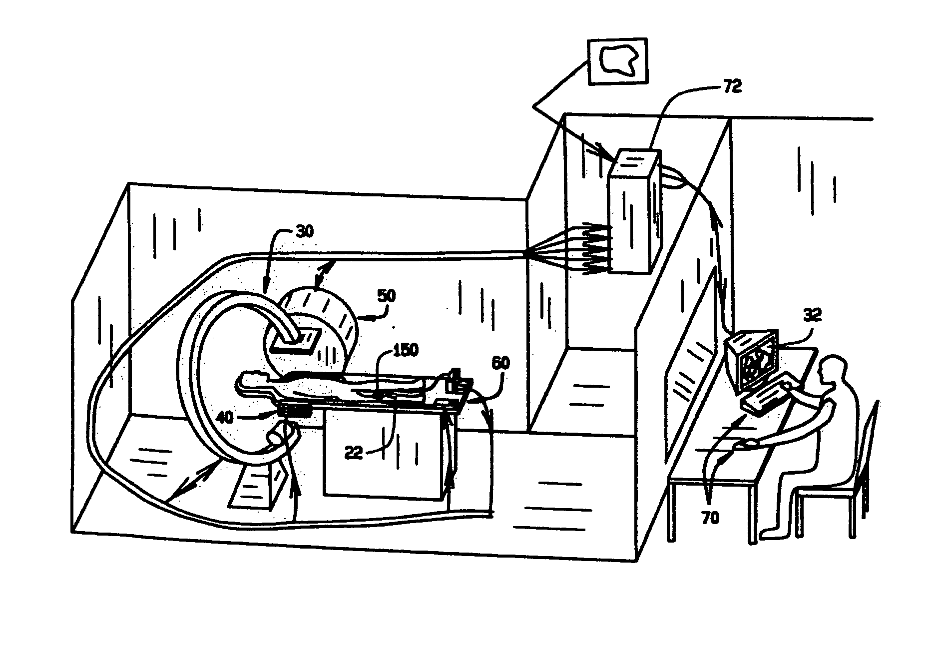
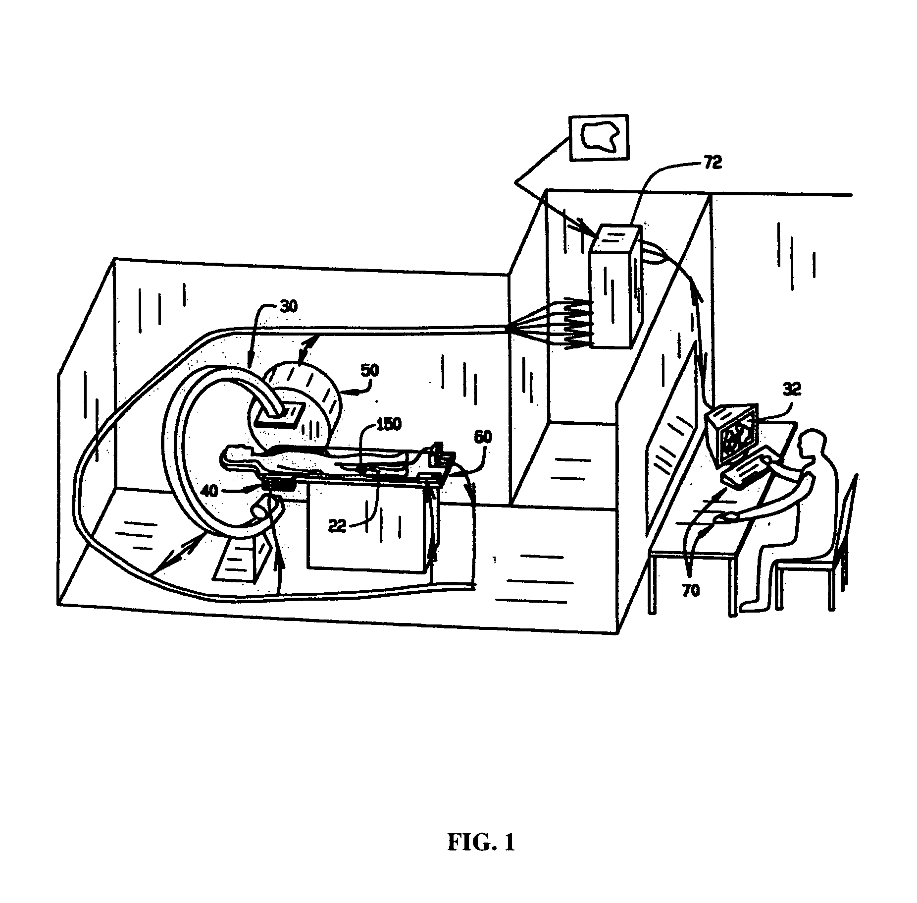
[0017]An automated system for navigating a medical device through the lumens and cavities in an operating region in a patient in accordance with the principles of this invention is indicated generally as 20 in FIG. 1. The system 20 comprises an elongate medical device 22, having a proximal end and a distal end adapted to be introduced into the operating region in a subject. The system 20 also comprises an imaging system 30 for displaying an image of the operating region on a display 32, including a representation of the distal end of the medical device 22 in the operating region.

[0018]The system also includes a navigation system for manipulating the distal end of the medical device 22. In this preferred embodiment the navigating system is a magnetic navigation system 50. Of course, the navigation system could alternatively be a piezoelectric system or a mechanical guide wire system or other suitable system for orienting the distal tip of the medical device. The magnetic navigation s...


PUM


Abstract

The present invention provides a means for guiding a medical device within the body to approach a target destination. The system and method provide a means for determining a predicted length and orientation, navigating the device to an intermediate point less than the predicted length, determining an error between the projected destination and actual target destination, and successively updating a predicted value of a control variable to yield an orientation within a predetermined distance error before advancing the device the remaining distance to the destination. This provides a physician with the capability of verifying the device will be accurately guided to the target destination without trial and error. A method is also provided for intuitive navigation to targets with limited trial and error based on user-applied device orientation adjustments, where the user chooses the magnitude of the adjustments and the system determines the adjustment direction.

Description

CROSS REFERENCE TO RELATED APPLICATION[0001]This application is a continuation of U.S. application Ser. No. 10 / 844,056, filed May 12, 2004, which is based on PCT Patent Application Ser. No. PCT / US03 / 10893, filed Apr. 9, 2003, which claims priority to U.S. Provisional Application Ser. No. 60 / 371,555, filed Apr. 10, 2002, all of which has been incorporated herein by reference.FIELD OF THE INVENTION[0002]This invention relates to a system and methods for interventional medicine, and more specifically to navigation of catheter and medical devices through the body to an operating region.BACKGROUND OF THE INVENTION[0003]Interventional medicine is the collection of medical procedures in which access to the site of treatment is made through one of the patient's blood vessels, body cavities or lumens. For example, angioplasty of a coronary artery is most often performed using a catheter which enters the patient's arterial system through a puncture of the femoral artery in the groin area. The...

Claims


Application Information

Patent Timeline
Patent Type & Authority Patents(United States)
IPC IPC(8): A61B19/00A61B17/00A61F11/00A61B17/22
CPCA61B6/463A61B19/56A61B19/20A61B2019/2265A61B19/52A61B19/00A61B6/12A61B2019/507A61B19/5244A61B1/00147A61B17/22A61B2019/5251A61B2017/003A61B6/4441A61B2018/00839A61B2019/5454A61B2019/2253A61B2019/5238A61B19/22A61B6/5235A61B6/466A61M25/0108A61B90/10A61B34/73A61B2034/733A61B90/36A61B34/20A61B34/70A61B34/25A61B2090/376A61B90/00A61B2034/107A61B2034/2051A61B2090/3954
Inventor VISWANATHAN, RAJU R.BLUME, WALTER M.
Owner STEREOTAXIS
Why Eureka
Try Eureka