
Laser pulse temporal, spectral and spatial shaping devices based on volume diffractive gratings with spatially variable parameters

a technology of spatial parameter and spectral parameter, applied in the field of laser systems, can solve the problems of reducing the delay time, affecting the accuracy of the delay time, so as to achieve the effect of increasing the delay tim

Inactive Publication Date: 2014-05-13
UNIV OF CENT FLORIDA RES FOUND INC +1
View PDF9 Cites 9 Cited by
  • Summary
  • Abstract
  • Description
  • Claims
  • Application Information

AI Technical Summary

Benefits of technology

This patent describes methods and systems to use dispersive devices, such as complex chirped volume Bragg gratings and reflectors combined with amplitude and phase masks, to increase the stretching and compression time of laser pulses in the temporal, spectral, and spatial domains. This enables greater productivity of laser systems in industrial environments and enables military applications of these lasers for remote sensing and weapons. The invention also provides methods to increase the average power and pulse energy of lasers for industrial and military use. Additionally, the invention compensates for grating vector fluctuations by applying a localized pressure to the grating or using a different material or wavelength to eliminate or control the fluctuations. The invention has applications in both civilian and military markets.

Problems solved by technology

Direct optical amplification of high-power ultrashort pulses results in detrimental nonlinear effects and laser-induced damage of amplifying medium due to extremely high peak power of amplified pulses.
However, a problem with the prior art is that sizes of such stretchers and compressors are large than sizes of amplifiers and the average power of such laser systems is limited by the relatively low damage threshold of the metal-coated gratings.
However, the maximum aperture of fiber chirped gratings does not allow achieving high power laser systems because of the laser induced damage of fibers by the compressed pulse.
However, no practical ways for making such gratings were described in that patent.
The optical path length differences between the different spectral components leads to a wavelength-dependent group delay.
However, there are several problems that still restrict a further increase of brightness, power and pulse energy in ultrashort laser systems with chirped pulse amplification.
The first problem is a limitation of a stretching time resulting from a technologically limited thickness of chirped Bragg gratings.
However, it results in a dramatic complication of stretching and compression devices.
The second problem is spectral phase distortions in stretched and compressed pulses resulting from deviations of stretching time from linear dependence on wavelength (nonlinear chirps) in different types of stretchers and compressors, from different linear and nonlinear dispersion functions in different components of chirped pulse amplification systems (fibers, amplifiers, phase retarders, etc.), and from technological imperfections of available stretchers and compressors (fibers, waveguides, surface gratings and volume gratings).
However since such configurations are bulky, it is not usable outside a laboratory environment.
Moreover, this approach cannot be used for compact and robust pulse stretchers and compressors based on chirped volume Bragg gratings.
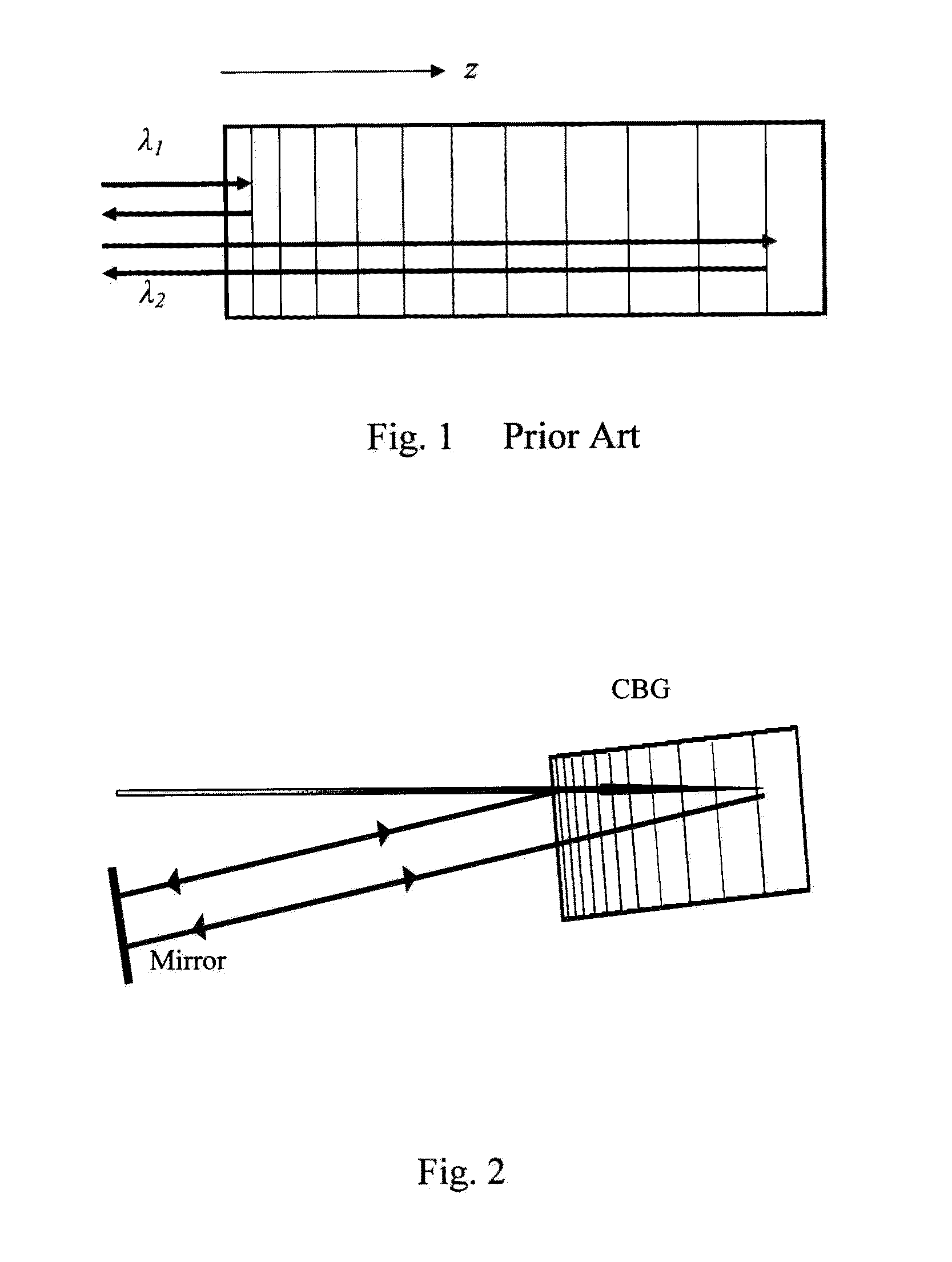
The third problem is keeping a normal incidence of incident and diffracted beams in respect to planes of constant refractive index of CBGs.
It is obvious for anyone skilled in the art that if the reflected beam in this conventional CBG configuration forms a sufficiently large angle θ with respect to the incident beam then the reflected beam will acquire lateral walk off, thus producing an unacceptable distortion of the output beam.
If this condition is not met the reflected beam will be unacceptably distorted.
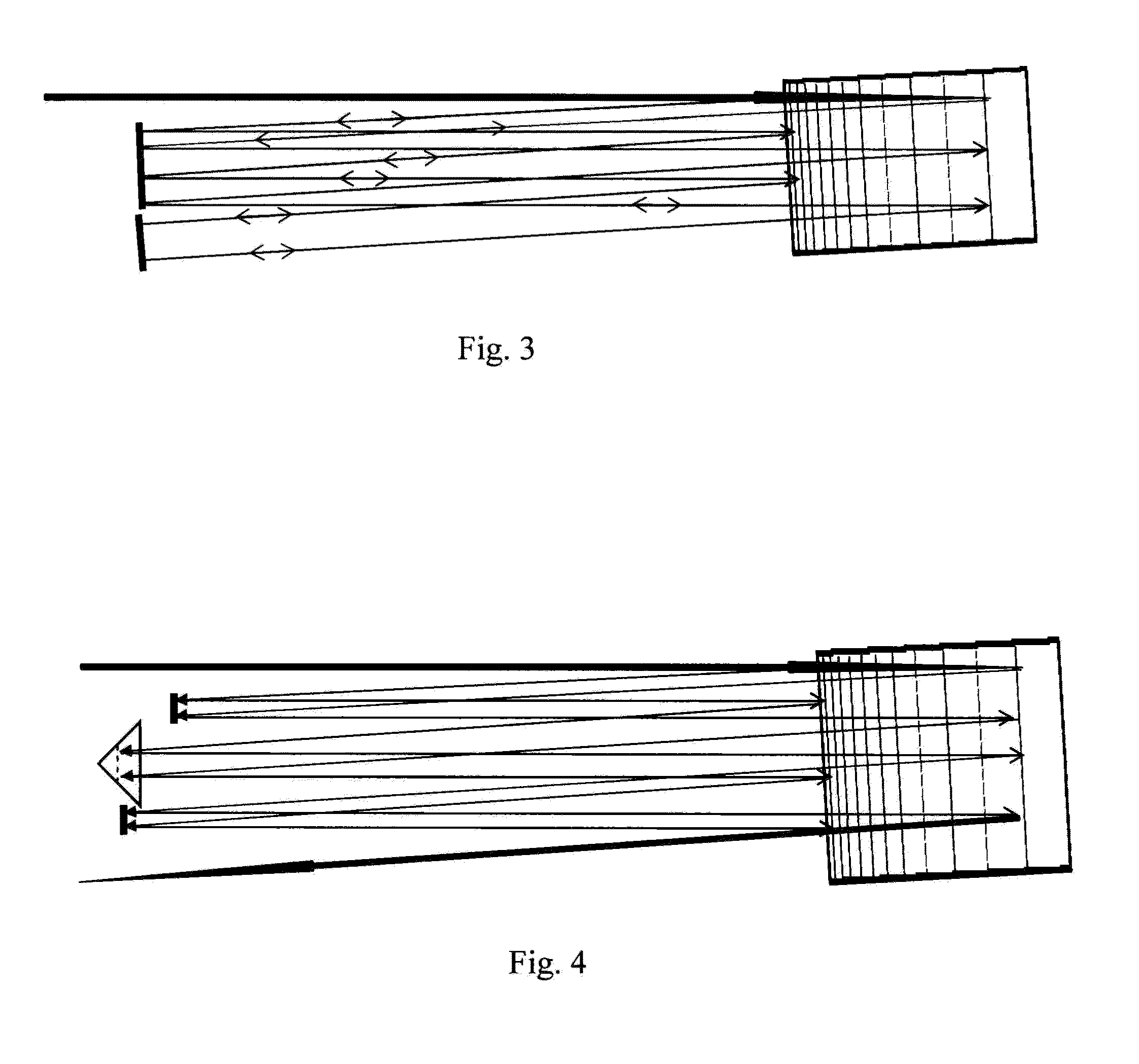
Essential practical limitation of operating at such small angles is that it becomes necessary to use large separation S between any pick-up or folding mirror and CBG.
This makes such a conventional multipass CBG arrangement very large, in contradiction to the intended technological goal.
In the '049 patent this was addressed by proposing complicated beam-switching arrangements, which make the conventional CBG multi-pass arrangement very complicated and difficult to implement in practice.
This is the simplest solution but it does not provide an opportunity for effective temporal, spatial and spectral control of processed laser pulses.
However, this consideration is not correct because this inclined grating is not reciprocal and, therefore, different spectral components of a laser pulse incurs different lateral walk off (it is described above) and spatial profile of a laser pulse will be dramatically distorted.

Method used


Image

  • Laser pulse temporal, spectral and spatial shaping devices based on volume diffractive gratings with spatially variable parameters
  • Laser pulse temporal, spectral and spatial shaping devices based on volume diffractive gratings with spatially variable parameters
  • Laser pulse temporal, spectral and spatial shaping devices based on volume diffractive gratings with spatially variable parameters

Examples


Embodiment Construction

[0056]Before explaining the disclosed embodiments of the present invention in detail it is to be understood that the invention is not limited in its application to the details of the particular arrangements shown since the invention is capable of other embodiments. Also, the terminology used herein is for the purpose of description and not of limitation.

[0057]The main restriction to generating high-power, high-energy, extremely short laser pulses is the appearance of nonlinear processes in laser amplifiers, including laser induced breakdown. The main approach to mitigate the problem is to stretch an original pulse before final amplification and then compress it back after amplification, referred to as chirped pulse amplification (CPA).

[0058]The recent inventions of volume Bragg gratings with variable period (volume longitudinally chirped Bragg gratings in photo-thermo-refractive (PTR) glass has dramatically changed the design of high power femtosecond lasers. Replacing of bulky pair...


PUM

PropertyMeasurementUnit
thickaaaaaaaaaa
FWHMaaaaaaaaaa
FWHM bandwidthaaaaaaaaaa

Abstract

Recent invention of longitudinally chirped volume Bragg gratings has dramatically changed a design of high power femtosecond lasers. Replacing of bulky pairs of conventional surface gratings with compact and robust chirped volume Bragg gratings for stretching and compression of laser pulses in chirped-pulse-amplification systems enabled decrease of size and weight of those systems by several times. The methods and devices enable substantial increase of stretching time and compression to shorter pulses, enhancement of stretched and compressed beams quality by stationary or dynamic shaping of gratings, and shaping of laser pulses in both temporal and spectral domains.

Description

CROSS REFERENCE TO RELATED APPLICATIONS[0001]This application is a continuation-in-part of co-pending U.S. patent application Ser. No. 11 / 261,077, filed on Oct. 28, 2005, which claims the benefit of priority to U.S. Provisional Application No, 60 / 623,889 filed on Nov. 1, 2004, which is a continuation-in-part of U.S. application Ser. No. 10 / 665,339 filed on Sep. 19, 2003, now U.S. Pat. No. 7,326,500, which is a continuation-in-part of U.S. application Ser. No. 09 / 750,708 filed on Dec. 28, 2000, now U.S. Pat. No. 6,673,497, which is a continuation in part of U.S. application Ser. No. 09 / 648,293 filed on Aug. 24, 2000, now U.S. Pat. No. 6,586,141, which claims the benefit of priority to U.S. Provisional Application No. 60 / 174,432 filed on Jan. 4, 2000, and claims the benefit of priority to U.S. Provisional Application No. 61 / 294,566 filed on Jan. 13, 2010. The entire disclosure of each of the applications listed in this paragraph are incorporated herein by specific reference thereto.ST...

Claims


Application Information

Patent Timeline
Patent Type & Authority Patents(United States)
IPC IPC(8): G02F1/07H01S3/10
CPCH01S3/0057G02F1/07H01S3/10G02B5/1861G02B27/0977
Inventor ANDRUSYAK, OLEKSIYGALVANAUSKAS, ALMANTASGLEBOV, LEONID B.GLEBOVA, LARISSALUMEAU, JULIENMOKHOV, SERGIYROTARI, EUGENIUSMIRNOV, VADIM I.ZELDOVICH, BORIS YA
Owner UNIV OF CENT FLORIDA RES FOUND INC
Learn More