Precision optical frequency tunable laser

a laser and optical frequency technology, applied in the field of photonics, can solve the problems of poor operation stability, low cost, and inability to achieve the purpose of miniaturization

Inactive Publication Date: 2014-05-20
GP PHOTONICS INC
View PDF3 Cites 1 Cited by
  • Summary
  • Abstract
  • Description
  • Claims
  • Application Information

AI Technical Summary

Benefits of technology

[0040]The invention has the following advantages and positive effects:
[0041]In the invention, a narrow band tunable acousto-optic filter with optical frequency shift compensation, an active polarization rotator, a polarization beam splitter, two etalons both having a free spectrum range of 50 GHz and two total reflection mirrors are used to form two laser resonant sub-cavities to achieve stable laser output. The optical frequency tuning precision is smaller than 1 GHz within a wide spectrum range can be realized based upon the temperature-based frequency shift of the transmission spectrum peak of the etalons. The requirement on the filtering bandwidth of the tunable acousto-optic filter is reduced, fast tuning with 25 GHz frequency interval is achieved by the tunable acousto-optic filter, which is suitable for output with 50 GHz frequency interval, and the etalons having a free spectrum range of 50 GHz. Thus, the requirement on the transmission spectrum peak frequency interval density of the etalons is reduced, and the difficulty in manufacturing the tunable acousto-optic filter and the etalons are also significantly reduced. Moreover, the optical frequency tuning range by the temperature-based frequency shift of the transmission spectrum peak of the etalons is reduced to 25 GHz. As a result, the tuning speed is greatly increased. The invention provides a method to build a laser with no mechanical movement component, stable and reliable performance, low cost, compact size and easy installation and production, and can meet the requirement for small size and reliable operation under an extreme working environment. Furthermore, the invention can also be widely used in optical test, fiber optical communication, biology, medical instrument, fiber sensor network and other fields.

Problems solved by technology

There are typically three tuning technologies used in an external cavity tunable laser: 1) tuning is achieved by using a precision stepping motor to drive a grating to rotate, and this technology has the following shortcomings: first, there are quite high requirements on stepping moving precision and repeatability of the stepping motor in achieving precision optical frequency tuning, thus the cost is relatively high; second, the purpose of miniaturization is hardly achieved due to the stepping motor used; and third, the operational stability is poor under a harsh working environment, in particular, resistances to various mechanical vibrations are poor.
Because of these problems, the tunable laser using this technology is only suitable for use under a laboratory working environment; 2) tuning is achieved by a tunable acousto-optic filter.
However, it has the shortcomings of low tuning precision and relatively wide filtering bandwidth, therefore, the tunable laser using this technology is only suitable for applications in which both the tuning precision and the output bandwidth are not high; and 3) tuning is based upon the temperature-sensitive characteristics of the transmission optical frequency of grating or other optical filtering devices in laser resonant cavity, such as an optical Etalon.
This tuning technology has high tuning precision and relatively narrow spectrum bandwidth, but low tuning speed.
Therefore it is not suitable when the wide spectral range tuning is needed, for example: if the temperature coefficient of an optical filtering device is 0.02 nanometers / degree, the desired spectrum range and temperature adjustment range are 20 nanometers and 100 degrees respectively, which is impracticable for some applications.

Method used


Image

  • Precision optical frequency tunable laser
  • Precision optical frequency tunable laser
  • Precision optical frequency tunable laser

Examples


Embodiment Construction

[0022]It is an objective of the invention to overcome the shortcomings in the prior art and to provide a precision optical frequency tunable laser with stable performance, low cost, small size, easy installation and production.

[0023]The technical scheme below is adopted by the invention for solving the technical problems in the prior art.

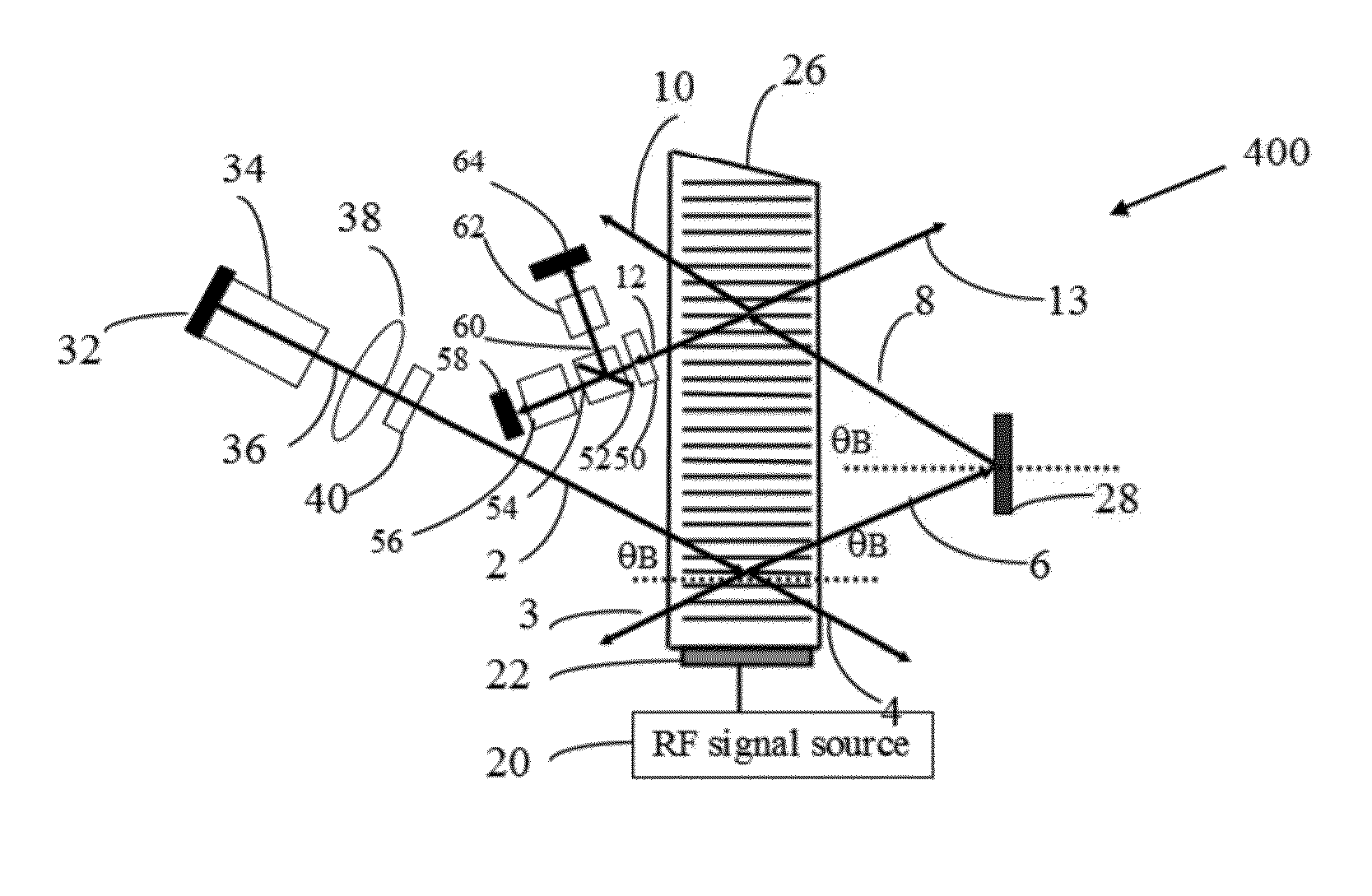
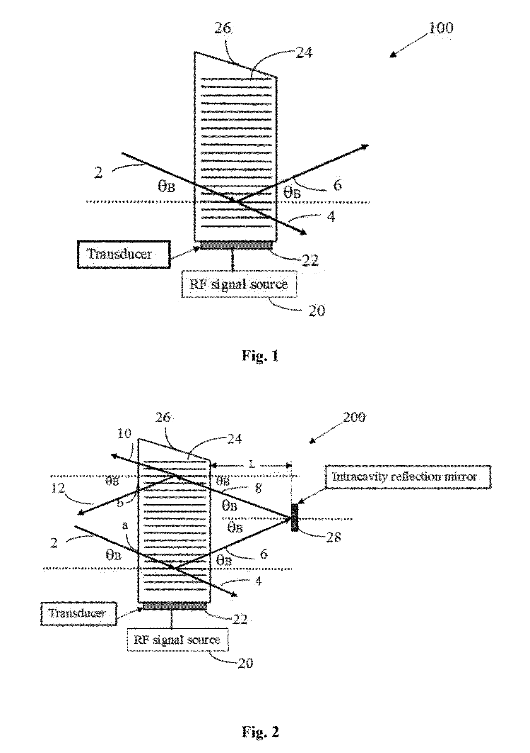
[0024]A precision optical frequency tunable laser comprising a laser gain medium, a laser cavity end mirror arranged on the laser gain medium, an intracavity collimating lens, an active optical phase modulator, a tunable acousto-optic filter and an intracavity total reflection mirror all arranged sequentially inside the laser cavity and in such a way that the light beam emitted from the laser gain medium can be diffracted twice by the tunable acousto-optic filter and the frequency shift introduced by the diffractions can be compensated, the laser further includes:

[0025]an active polarization rotator for controlling the polarization direction of line...


PUM


Abstract

The invention relates to a precision optical frequency tunable laser. The laser includes: a laser gain medium, an intracavity collimating lens, an active optical phase modulator, a tunable acousto-optic filter and an intracavity total reflection mirror all arranged sequentially in a laser cavity, and the tunable laser further includes an active polarization rotator, a polarization beam splitter, two etalons, a temperature control system attached to the etalons, two total reflection mirrors, a radio frequency signal source, a laser pumping source, an active optical phase modulator drive source, an active polarization rotator drive source and a laser drive control circuit. Through the temperature control system attached to the etalons, stable laser output and the precision optical frequency tuning less than 1 GHz within a wide spectrum range can be realized, thereby greatly reducing the bandwidth requirements in achieving narrowband filtering for the tunable acousto-optic filter. The invention is compact with high performance, low cost for volume production and installation, and achieves stable tunable laser output within a wide spectrum range.

Description

CROSS-REFERENCE TO RELATED APPLICATION[0001]The application is a continuation of PCT / CN2011 / 077124 (filed on Jul. 14, 2011), which claims priority of Chinese patent application 201110193688.6 (filed on Jul. 12, 2011), the contents of which are incorporated herein by reference, as if fully set forth herein.FIELD OF THE INVENTION[0002]The invention belongs to the field of photonics, and in particular relates to a precision optical frequency tunable laser.BACKGROUND OF THE INVENTION[0003]There are typically three tuning technologies used in an external cavity tunable laser: 1) tuning is achieved by using a precision stepping motor to drive a grating to rotate, and this technology has the following shortcomings: first, there are quite high requirements on stepping moving precision and repeatability of the stepping motor in achieving precision optical frequency tuning, thus the cost is relatively high; second, the purpose of miniaturization is hardly achieved due to the stepping motor us...

Claims


Application Information

Patent Timeline
Patent Type & Authority Patents(United States)
IPC IPC(8): H01S3/10
CPCH01S3/082H01S3/0817H01S5/142H01S3/107H01S3/1068H01S3/106H01S3/08054H01S3/08036H01S3/1062
Inventor GAO, PEILIANG
Owner GP PHOTONICS INC
Why Eureka
Try Eureka