Exhaust gas purification filter

a technology of exhaust gas and filter, which is applied in the direction of filtration separation, ceramicware, separation processes, etc., can solve the problems of low trapping efficiency and inability to apply techniques, and achieve the effects of reducing the thickness of the partition wall, suppressing the rise in pressure loss, and reducing the amount of particulate matter contained

Active Publication Date: 2014-05-27
NGK INSULATORS LTD
View PDF16 Cites 10 Cited by
  • Summary
  • Abstract
  • Description
  • Claims
  • Application Information

AI Technical Summary

Benefits of technology

[0018]The present invention has been made in view of the prior art problems and aims to provide an exhaust gas purification filter capable of being suitably used for an engine, particularly, an engine having a reduced amount of particulate matter contained in exhaust gas and capable of appropriately removing particulate matter in exhaust gas with suppressing the rise in pressure loss.
[0019]As a result of earnest studies to solve the aforementioned problems, the present inventor found out that an exhaust gas purification filter configured as described below enables to suppress the rise in pressure loss while satisfying the required trapping efficiency, which has lead to the completion of the present invention. That is, in an exhaust gas purification filter for an engine having less particulate matter in exhaust gas than a conventional diesel engine and having a relatively low required trapping efficiency, it is effective not to sharpen the pore size distribution of the partition walls as described in Japanese Patent No. 3272746, but to broaden the pore size distribution, in reverse. Further, it is effective to specify the thickness and the average pore size of the partition walls in predetermined ranges and further dispose a specific surface trapping layer on the surfaces of the partition walls, thereby being able to suppress the rise in pressure loss with satisfying the aforementioned required trapping efficiency. According to the present invention, there is provided an exhaust gas purification filter shown below.
[0025]An exhaust gas purification filter of the present invention is provide d with a honeycomb structure having porous partition walls, plugging portions disposed in one side open end portions of predetermined cells and in the other side open end portions of the other cells, and a surface trapping layer disposed on the surface of each of the cells having open end portions on an exhaust gas inflow side of the honeycomb structure. In an exhaust gas purification filter of the present invention, the partition walls have a thickness of 0.05 mm or more and 0.18 mm or less and an average pore size of 10 μm or more and 18 μm or less, which is measured by mercury porosimetry. Further, in an exhaust gas purification filter of the present invention, the proportion of the volume of the pores having a size of twice the average pore size or more in the entire pore volume in a pore size distribution of the partition walls measured by mercury porosimetry is 5% or more and 40% or less. Further, In an exhaust gas purification filter of the present invention, the surface trapping layer has an average pore size of 0.1 μm or more and 5 μm or less, a porosity of 50% or more and 80% or less, and a thickness of 1 μm or more and 50 μm or less. By thus specifying the proportion of the volume of the pores having a size of twice the average pore size or more in the entire pore volume in the average pore size distribution of the partition walls (i.e., 5% or more and 40% or less), the pore size distribution of the partition walls is broadened in comparison with the pore size distribution of the partition walls in a conventional diesel engine filter. In addition, in an exhaust gas purification filter of the present invention, the thickness of the partition walls is reduced (i.e., 0.05 mm or more and 0.18 mm or less) in comparison with a conventional diesel engine filter, and the average pore size measured by mercury porosimetry is in a specific range (i.e., 10 μm or more and 18 μm or less). By such a shape of a pore size distribution, partition wall thickness, and average pore size, effects of them are combined to be able to remove particulate matter in exhaust gas in a good manner while suppressing the rise in pressure loss in an engine having a reduced amount of particulate matter contained in exhaust gas.
[0026]Further, in an exhaust gas purification filter of the present invention, a surface trapping layer having the aforementioned average pore size, porosity, and thickness is disposed on the surface of each of the cells open in the exhaust gas inflow side end portions. The surface trapping layer enables to improve the trapping efficiency in a good manner without extremely raising the pressure loss of the exhaust gas purification filter. Therefore, an exhaust gas purification filter of the present invention is an exhaust gas purification filter suitable for exhaust gas regulations in an engine having a small amount of particulate matter in exhaust gas in comparison with a conventional general diesel engine. Examples of the engine having a small amount of particulate matter include a direct gasoline-injection engine, a natural gas compression ignition type engine, and an advanced technological diesel engine (e.g., diesel engine having improved combustion).

Problems solved by technology

Therefore, in a filter used for such an engine, the required trapping efficiency is set to be low in comparison with the case of the aforementioned diesel engine.
Therefore, there is a problem of impossible application of the technique described in Japanese Patent No. 3272746, which is most suitable for a conventional diesel engine, as it is to an engine having a reduced particulate matter amount.

Method used


Image

  • Exhaust gas purification filter
  • Exhaust gas purification filter
  • Exhaust gas purification filter

Examples


example 1

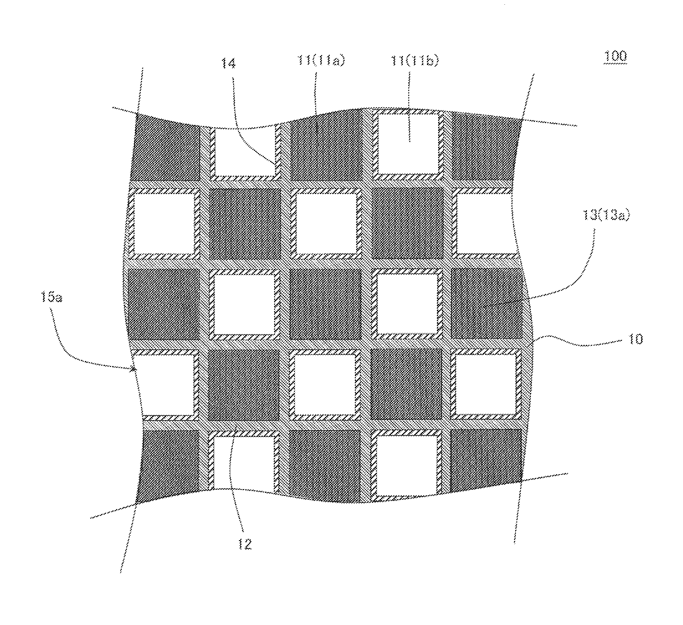
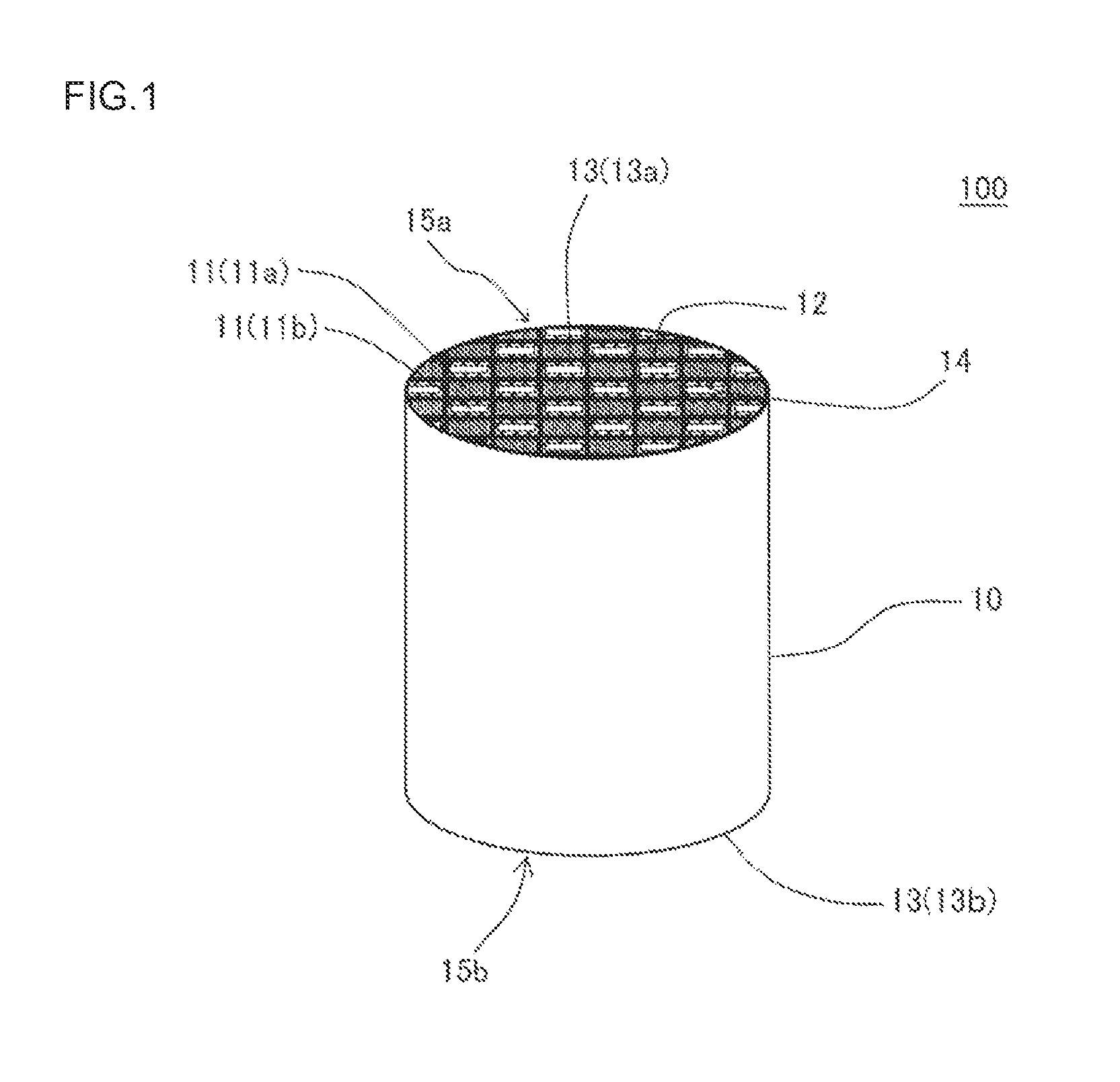
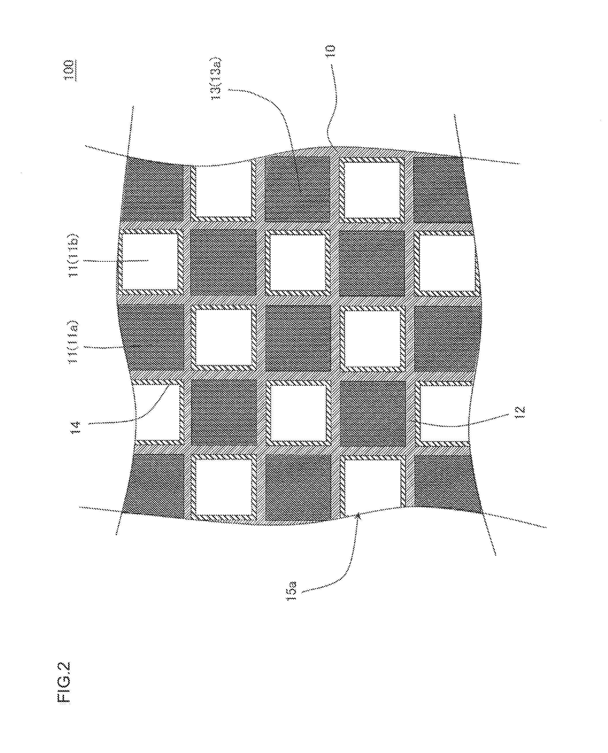
(1) Manufacture of Exhaust Gas Purification Filter:

[0104]In the first place, a honeycomb structure used for an exhaust gas purification filter was manufactured. Specifically, as the cordierite-forming raw materials, there were used alumina, aluminum hydroxide, kaolin, talc, and silica. Specifically, to 100 parts by mass of the cordierite-forming raw material were added 35 parts by mass of a dispersion medium, 6 parts by mass of an organic binder, and 0.5 part by mass of a dispersant, and they were mixed and kneaded to prepare a forming kneaded material. Water was used as the dispersion medium, hydroxypropylmethyl cellulose was used as the organic binder, and ethylene glycol was used as the dispersant.

[0105]In Example 1, the average particle diameter of talc was 20 μm, and the average particle diameter of silica was 25 μm.

[0106]The forming kneaded material prepared above was extruded to obtain a honeycomb formed body. The honeycomb formed body was dried by the use of a microwave drie...


PUM

PropertyMeasurementUnit
thicknessaaaaaaaaaa
thicknessaaaaaaaaaa
porosityaaaaaaaaaa

Abstract

An exhaust gas purification filter 100 includes: a honeycomb structure 10 having partition walls 12, plugging portions 13, and a surface trapping layer 14 having an average pore size of 0.1 μm or more and 5 μm or less, a porosity of 50% or more and 80% or less, and a thickness of 1 μm or more and 50 μm or less. The partition walls 12 have a thickness of 0.05 mm or more and 0.18 mm or less and an average pore size of 10 or more and 18 μm or less, and the proportion of the volume of the pores having a size of twice the average pore size or more in the entire pore volume in a pore size distribution of the partition walls 12 is 5% or more and 40% or less.

Description

BACKGROUND OF THE INVENTION[0001]1. Field of the Invention[0002]The present invention relates to an exhaust gas purification filter. More specifically, the present invention relates to an exhaust gas purification filter suitably used for removing particulate matter contained in exhaust gas discharged from an engine.[0003]In recent years, there has been demanded reduction in fuel consumption of an automobile from the viewpoints of influences on the global environment and resource saving. Therefore, internal combustion engines having good thermal efficiency, such as a diesel engine and a direct gasoline-injection engine tend to be used as a powder source for an automobile.[0004]On the other hand, in these internal combustion engines, soot generation upon combustion is a problem. There is required a countermeasure to inhibit particulate matter such as the aforementioned soot from being released from the viewpoint of the air environment.[0005]As a measure for inhibiting the aforemention...

Claims


Application Information

Patent Timeline
Patent Type & Authority Patents(United States)
IPC IPC(8): B01D39/06B01D50/00B01D24/00B01D39/14
CPCB01D2046/2496F01N2330/48B01D46/2429C04B2111/00793B01D2046/2437F01N3/0222B01D2046/2433F01N2330/30C04B38/0009B01D46/2498B01D46/24492B01D46/24491C04B35/195C04B38/0064C04B38/0074B01D46/2459B01D46/2484B01D46/2455B01D46/2474B01D46/2482
Inventor MIYAIRI, YUKIO
Owner NGK INSULATORS LTD
Why Eureka
Try Eureka