
Capactive pressure sensor incorporating a temperature measurement and compatible with hot environments

a temperature measurement and capactive pressure sensor technology, applied in the direction of measuring devices, instruments, fluid pressure measurement using capacitance variation, etc., can solve the problems of optimum conditions, amplitudes that can be considerable, and uncertainty on pressure measurement is simply reduced but remains significan

Active Publication Date: 2014-07-08
FOGALE NANOTECH SA
View PDF12 Cites 49 Cited by
  • Summary
  • Abstract
  • Description
  • Claims
  • Application Information

AI Technical Summary

Benefits of technology

The invention is a device that uses a capacitive sensor to measure temperature accurately in noisy environments. It uses an active guard technique to protect the sensor from external disturbances and reduce errors caused by stray capacitances. The device can measure temperature in various applications such as pressure sensors, vane clearances, and can provide useful information to operators for performing more relevant diagnostics on the system under test. This reduces the number of temperature sensors and corrects thermal drift in the sensor. The device uses a membrane material that has an expansion coefficient close to that of the entire sensor to limit stresses and deformations that cause errors and risks of sensor degradation.

Problems solved by technology

The problem is that all these parameters strongly depend on temperature, the variation amplitudes of which can be considerable in targeted applications.
However, when temperature is unknown, the uncertainty on the pressure measurement is simply reduced but remains significant.
In other words, it is juxtaposed rather than integrated to the sensor and is thus not in optimum conditions, in terms of measurements (the measured temperature can significantly differ from that of the membrane) as well as in terms of mechanical integration (the connections are bulky).
However, this sensor can only be used for dynamic measurements of capacitance variations.
Indeed, the method being used results in stray capacitances in the cable, which are variables and several orders of magnitude higher than the capacitance measured by the sensor.
This problem in part comes from the guardless coaxial configuration of the sensor.
The integration of the thermocouple such as described in EP0334441 thus results in a degradation of the sensor performance which is unacceptable for static or absolute precision measurements and therefore, de facto, the solution provided in EP0334441 is not applicable to pressure measurements.
The problem is all the more significant that in applications of measurements on turbines, the cable should generally be several meters long to be able to offset electronics from hot areas.

Method used


Image

  • Capactive pressure sensor incorporating a temperature measurement and compatible with hot environments
  • Capactive pressure sensor incorporating a temperature measurement and compatible with hot environments
  • Capactive pressure sensor incorporating a temperature measurement and compatible with hot environments

Examples


first embodiment

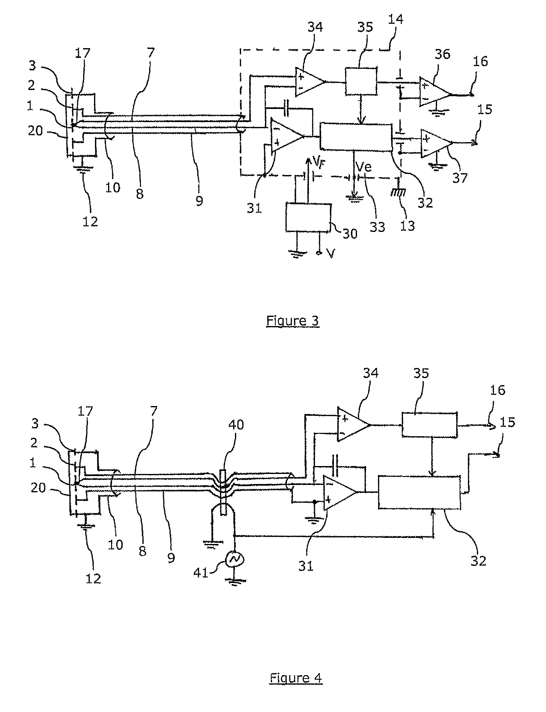
[0078]FIG. 3 illustrates the electronics of a pressure sensor equipped with a thermocouple, based on floating bridge electronics,

second embodiment

[0079]FIG. 4 illustrates the electronics of a pressure sensor equipped with a thermocouple, based on a transformer guard generation.

[0080]According to a preferable but in no way limiting embodiment, the device according to the invention is substantially cylindrical. The embodiment shown enables sensors operating at temperatures higher than 600° C. to be made.

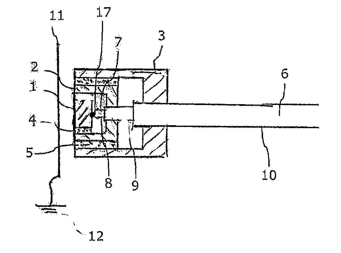
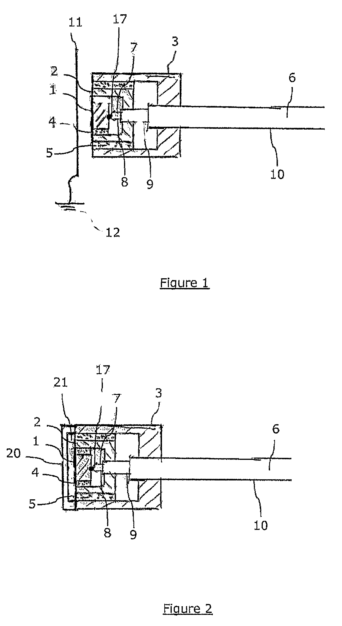
[0081]In reference to FIG. 1, the capacitive sensor comprises the following elements:[0082]a measurement electrode 1, which may be made of platinum, a Dilver type alloy, a refractory metal alloy or a superalloy,[0083]a guard electrode 2, which may be made of platinum, a Dilver type alloy, a refractory metal alloy or a superalloy,[0084]a body 3, which may be made of platinum, a Dilver type alloy, or a refractory metal alloy or a superalloy,[0085]dielectric rings 4 and 5, which can be made of refractory ceramics, for example alumina-(Al2O3) or boron nitride-(NB) based,[0086]a triaxial cable 6, which comprises two sensor conductors...


PUM

PropertyMeasurementUnit
temperatureaaaaaaaaaa

Abstract

A capacitive measurement device including first measurement device designed to carry out a first measurement function in relation to a nearby object, the first measurement device including a body and, a capacity electrode, both of a substantially conductive material, and a guard electrode placed between the body and the capacitive electrode and insulated from the body on the one hand and from the capacitive electrode on the other hand by dielectric elements; an excitation apparatus which maintains the capacitive electrode and the guard electrode to a desired AC electrical potential; a first electronic apparatus, connected to the capacitive and guard electrodes, for measuring the capacitance between the capacitive electrode and the object; and a second measurement device designed to carry out a second measurement function, which are located in the vicinity of either the capacitive or guard electrode, and maintained by the excitation apparatus to a desired AC electrical potential.

Description

TECHNICAL FIELD[0001]The present invention relates to a capacitive pressure sensor compatible with low to high temperature applications which integrates a temperature probe.[0002]The field of the invention is more particularly but in a non-limiting way the one of gas turbine instrumentation, as well as aircraft reactors but also the nuclear, automotive and offshore fields.STATE OF PRIOR ART[0003]Gas turbine manufacturers use pressure sensors to check the behaviour of turbines on a test bench upon development but also upon use. Temperatures often exceed 600° C. and the pressure measurement is carried out by sensors being offset in areas where the temperature does not exceed a few hundreds degrees. This technique requires heavy mechanical interfaces and the pressure dynamic measurement can be degraded because of the transfer function of the mechanical interface.[0004]Manufacturers increasingly want to carry out a static and dynamic pressure measurement in situ, that is in areas the te...

Claims


Application Information

Patent Timeline
Patent Type & Authority Patents(United States)
IPC IPC(8): G01L9/12
CPCG01D21/02G01L19/04G01L9/12G01L9/0072G01D5/24G01L9/125
Inventor ROZIERE, DIDIER
Owner FOGALE NANOTECH SA
Learn More