
Remedial system: a pollution control device for utilizing and abating volatile organic compounds

a pollution control device and volatile organic compound technology, applied in the direction of gaseous fuels, machines/engines, separation processes, etc., can solve the problems of unsafe operation, environmental damage or health problems, and present form of oxidizers that are too polluting, etc., to achieve safe use, treatment and/or disposal of vocs

Active Publication Date: 2014-07-15
INNOVATIVE ENVIRONMENTAL SOLUTIONS LLC DBA REMEDIATION SERVICE INTL
View PDF28 Cites 157 Cited by
  • Summary
  • Abstract
  • Description
  • Claims
  • Application Information

AI Technical Summary

Benefits of technology

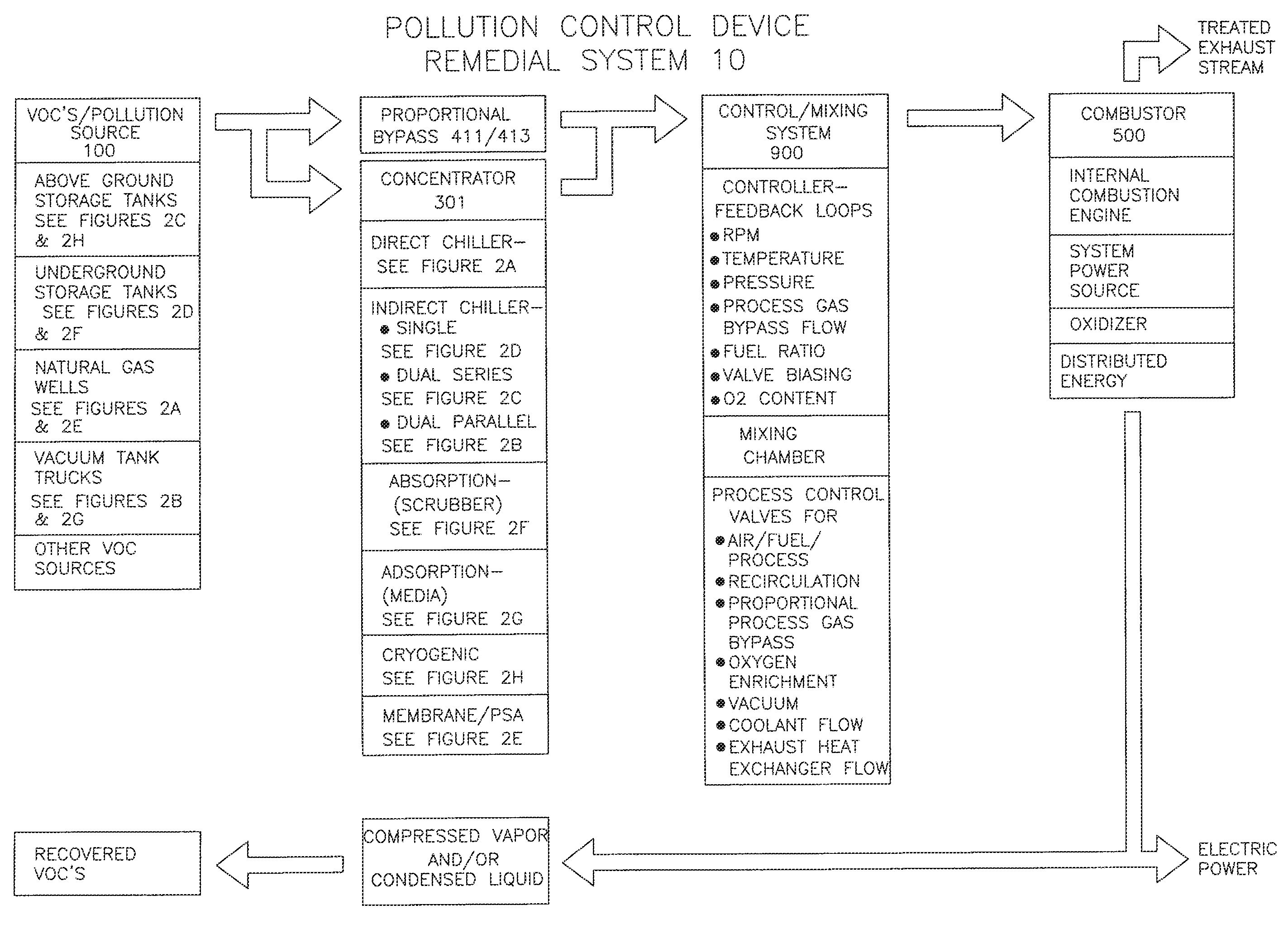
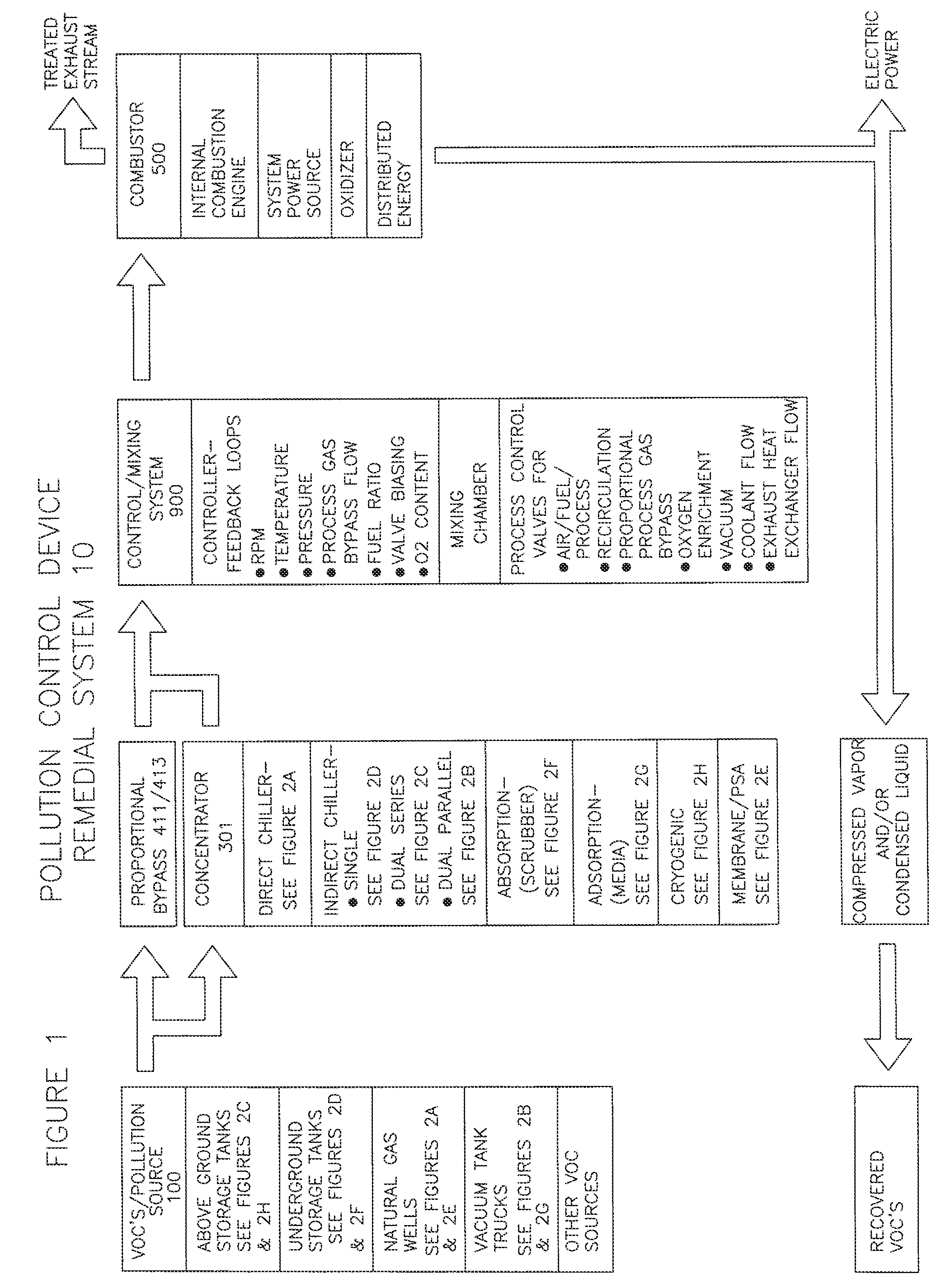
The present invention is a remedial pollution system that can capture and use energy from the process vapor stream of various industrial processes, oil and gas production fields, and vessel storing hydrocarbons. The system includes a concentrator for reducing energy in the process gas and an ICE for generating energy from the remaining process gas. The generated power can be used to operate a compressor and oxygen-nitrogen separator to inert the process for safety considerations and to inject stripped oxygen downstream in the process. The system can also be used to abate fumes from vehicles and underground storage tanks and produce a VOC condensate that can be reused as a fuel source or produce energy that can be put back into the energy grid.

Problems solved by technology

Air displaced in the process becomes saturated with vapors containing VOCs and SVOCs that can cause environmental damage or health issues.
Recently implemented environmental regulations or changes to existing regulations have made the present form of oxidizers either too polluting, unsafe to operate, too expensive or obsolete.
Alternatively, VOCs and SVOCs can be removed and controlled by adsorption onto activated carbon, but excessive cost and handling are of concern due to the large volumes of carbon typically required for proper abatement.
While carbon adsorption is not adversely affected by a change in air fuel mixture, safety and control limitations for current oxidation technologies such as flares, thermal / catalytic oxidizers and conventional ICE's can require significant and expensive amounts of alternate fuel source in order to combust the VOCs and SVOCs in the vapor stream.
In addition, traditional oxidizers are usually physically large in size and are oversized in order to handle fluctuation of the BTU content of the vapor stream.
As a result, traditional oxidizers burn excessive amounts of alternate fuel, and therefore generate significant amount of greenhouse gas emissions without effectively recovering the energy available from the VOCs and SVOCs in the vapor stream.
Similarly, the adsorption of organic compounds onto an activated carbon process bed requires a large footprint storage container.
This reprocessing requires energy (alternate fuel source), generates additional waste streams and produces greenhouse gas emissions.
Furthermore, carbon is unsafe for processing high VOC content vapor streams because the carbon may easily ignite.
However, it does not have the capability to handle the rapidly changing air flow volume / density and varying BTU concentrations found in the process vapor stream.

Method used


Image

  • Remedial system: a pollution control device for utilizing and abating volatile organic compounds
  • Remedial system: a pollution control device for utilizing and abating volatile organic compounds
  • Remedial system: a pollution control device for utilizing and abating volatile organic compounds

Examples


example 1

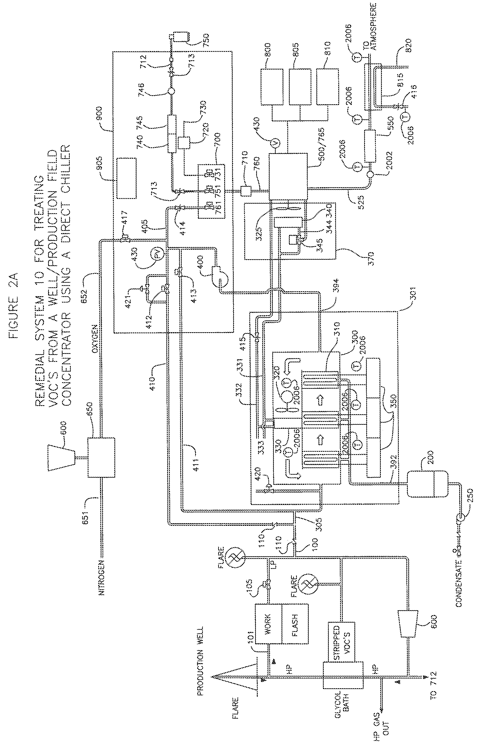
[0144]Remedial system 10 can be used in any number of various applications where there is a source of organic volatiles, VOCs. For example, it has been found that process gas that is routed to a flare for oxidation can instead be treated with remedial system 10 of the present invention and electricity generated as a byproduct of the inventions' oxidation process. In one exemplary embodiment, about 20% of a 60 SOW process gas stream going to a flare for oxidation is diverted to the remedial system. The diverted process gas stream is hooked up directly to an ICE 500. Control mixing system 900 and air fuel controller 905 on the ICE 500 creates a mix of about 99% of the process gas and 1% of propane alternate fuel to form a mixed fuel for combustion by the ICE 500. In the exemplary embodiment, the ICE 500 then is used to run a generator which produces between 25 to 40 kW of usable electricity for the site. In another embodiment, no gas will be directed to flare in favor of the invention...

example 2

[0145]In another exemplary embodiment, a process gas stream is directed to the condenser unit of the present invention. The condenser unit removes about 10 to 20% of the VOCs and SVOCs in the process gas stream at the initial stage of operation of the remedial system. At the steady state condition of remedial system 10, the condenser removes about 20% to 90% of the VOCs (depending on VOC type) in the process gas stream before it reaches the ICE 500. The net result, following oxidation by the ICE 500, is over 99.9% removal of VOCs in the process gas stream. In this exemplary embodiment, the ICE 500 is a single engine rated at less than 50 brake horsepower (BHP). Although an ICE with a larger engine or multiple engines can be used, it may not be necessary since the condenser unit removes most of the volatile contents from the process gas stream.

[0146]In view of the foregoing, an embodiment of the present invention provides a remedial system that has a concentrator adapted to remove a ...


PUM

PropertyMeasurementUnit
Poweraaaaaaaaaa
Volatilityaaaaaaaaaa

Abstract

A remedial pollution control system for treating volatile organic compounds that may include a vapor concentrator connected to a line that is laden with volatile organic compounds, the concentrator has an organic condensate output line and a vapor output line; a mixing chamber adapted to receive air provided from an air supply line, combustible fuel from an alternate fuel supply line, and a vapor stream from the vapor output line to produce a mixed fuel supplied to an internal combustion engine, a control mixing system with a controller for producing a proper air to fuel ratio in the mixed fuel supply, and power generated to operate other devices used to more efficiently abate volatile organic compounds and reduce greenhouse gas emissions.

Description

CROSS-REFERENCE TO RELATED APPLICATION(S)[0001]This application claims priority of U.S. Provisional Patent Application No. 61 / 054,452, filed May 19, 2008, the entire contents of which is incorporated herein by reference.BACKGROUND[0002]Vapor streams containing volatile and semi-volatile organic compounds (VOCs and SVOCs) are produced by industrial processes; as a result of the transfer of liquids from one containment body to another due to the displacement of air or liquid, by their volatilization during the industrial process or by contaminated soil remediation or other environmental cleanup operations. These processes typically use either vacuum or pressure pumps, blowers or compressors. Air displaced in the process becomes saturated with vapors containing VOCs and SVOCs that can cause environmental damage or health issues.[0003]Until most recently, control and destruction of these vapors was traditionally done with different pollution control devices that controlled and / or oxidiz...

Claims


Application Information

Patent Timeline
IPC IPC(8): F02B43/00
CPCF02B43/00Y02T10/32B01D5/009B01D53/005B01D53/047B01D53/1487B01D53/229B01D2257/702B01D2257/708B01D2258/06B01D2259/416B01D2259/4516F02B63/00F02D19/0671F02M21/0209F02M21/0218F02M21/0227F02M21/0287F02M25/00Y02T10/30Y02P70/10Y02A50/20C10L3/00C10L2290/10C10L2290/24C10L2290/30
Inventor ROY, MICHAEL J.NEILL, LAWRENCE
Owner INNOVATIVE ENVIRONMENTAL SOLUTIONS LLC DBA REMEDIATION SERVICE INTL
Learn More