Imaging apparatus and imaging system, method thereof and program for the same

a technology applied in the field of imaging apparatus and imaging system, can solve problems such as image quality degradation, and achieve the effect of reducing ghosts and preventing considerable image quality degradation

Active Publication Date: 2014-09-09
CANON KK
View PDF63 Cites 29 Cited by
  • Summary
  • Abstract
  • Description
  • Claims
  • Application Information

AI Technical Summary

Benefits of technology

[0011]The present invention has an advantageous effect capable of reducing a ghost (step of image) which may occur in an image provided by a driving operation of an FPD and which is affected by an irradiation area, and preventing considerable image quality degradation without complex image processing.
[0012]Further features of the present invention will become apparent from the following description of exemplary embodiments with reference to the attached drawings.

Problems solved by technology

Therefore, a ghost (step of image) affected by the irradiation area occurs in a provided image, which may cause image quality degradation.

Method used


Image

  • Imaging apparatus and imaging system, method thereof and program for the same
  • Imaging apparatus and imaging system, method thereof and program for the same
  • Imaging apparatus and imaging system, method thereof and program for the same

Examples


first embodiment

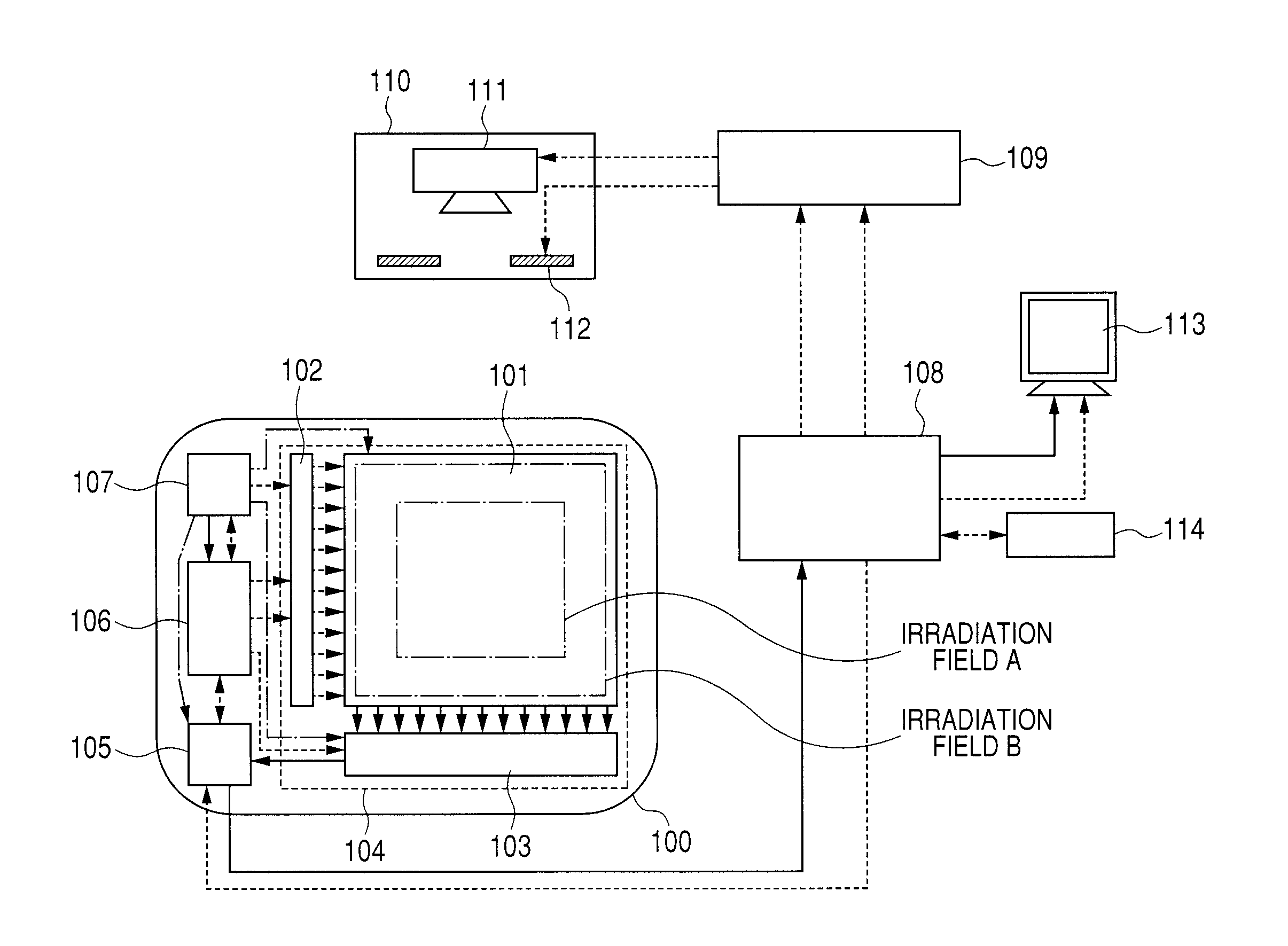
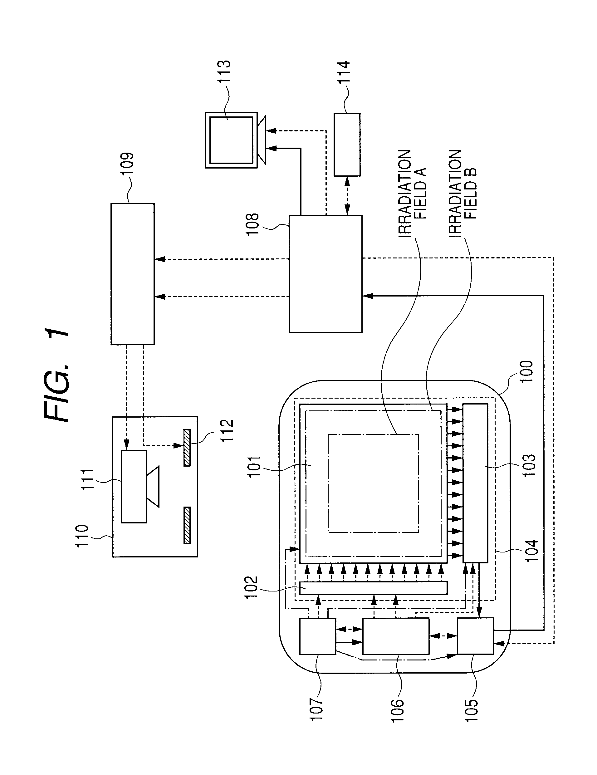
[0022]A radiation imaging system illustrated in FIG. 1 according to the present embodiment includes an imaging apparatus 100, a control computer 108, a radiation controlling apparatus 109, a radiation generator apparatus 110, a display 113, and a console 114. The imaging apparatus 100 includes a flat panel detector (FPD) 104 which includes a detecting unit 101 having a plurality of pixels for converting radiation or light into an electric signal, a driving circuit 102 for driving the detecting unit 101, and a read out circuit 103 for outputting as image data the electric signal from the detecting unit 101 driven. The imaging apparatus 100 further includes a signal processing unit 105 for processing the image data from the FPD 104 to output it, a control unit 106 for supplying an individual control signal to each of components to control an operation of the FPD 104, and a power source 107 for supplying an individual bias to each of the components. The signal processing unit 105 recei...

second embodiment

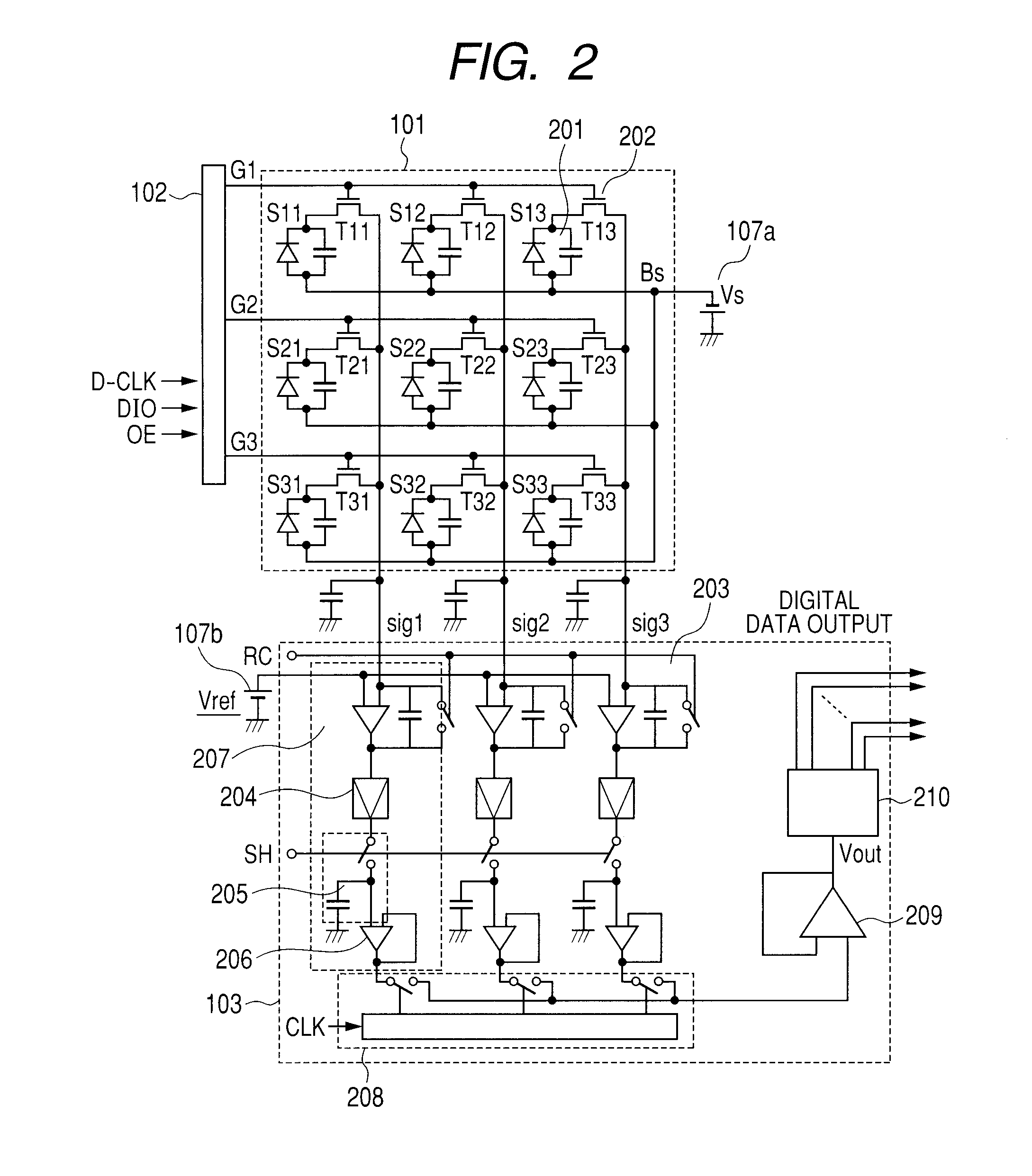
[0044]Next, with reference to FIGS. 6A and 6B, an imaging apparatus according to a second embodiment of the present invention will be described. Note that a like component as the first embodiment is shown by a like reference number, and detailed description thereof is omitted. Further, in FIG. 6A, similar to FIG. 2, for the simplicity, an imaging apparatus having an FPD including pixels arrayed in 3 rows and 3 lines is shown, but an actual imaging apparatus may have higher order multi-pixel.

[0045]The detecting unit 101 of the first embodiment uses a PIN photodiode as the conversion element 201, but a detecting unit 101′ of the embodiment uses an MIS type photoelectric conversion element of an MIS conversion element as a conversion element 601. Also, in the first embodiment, one pixel has one switching element for outputting provided therein, but in this embodiment, one pixel has, in addition to a switching element 602 for outputting, a switching element 603 for refreshing provided t...


PUM


Abstract

An imaging operation includes a first imaging operation for outputting image data according to irradiation to the detector with radiation or light in an irradiation field A corresponding to a part of the plurality of pixels, and a second imaging operation for outputting image data according to irradiation to the detector 104 with radiation or light in an irradiation field B wider than the irradiation field A, wherein, responsive to a changing from irradiation in the irradiation field A to irradiation in the irradiation field B, an operation of the detector is controlled so that the detector performs an initializing operation for initializing conversion elements during a period between the first and second imaging operations.

Description

TECHNICAL FIELD[0001]The present invention relates to an imaging apparatus and an imaging system. More particularly, the present invention relates to a radiation imaging apparatus and an imaging system used for a radiation imaging system that are preferably used for still image radiographing such as radiographing and moving image radiographing such as fluoroscopic radiographing in medical diagnostics. Note that radiation, in the present invention, includes, in addition to an alpha beam, a beta beam and a gamma beam which are beams made of a particle (including a photon) emitted due to radioactive decay, a beam having energy equal to or more than those beams have, such as an X-ray, a corpuscular ray and a cosmic ray.BACKGROUND ART[0002]Recently, a radiation imaging apparatus using a flat panel detector (FPD) formed of semiconductor material has began to be in a practical use as an imaging apparatus used for medical image diagnostics and non-destructive inspection through an X-ray. Su...

Claims


Application Information

Patent Timeline
Patent Type & Authority Patents(United States)
IPC IPC(8): G01J1/00
CPCG01T1/2928H04N5/32H04N5/343H04N5/3454H04N5/357H04N25/42H04N25/443H04N25/60
Inventor SATO, SHOENDO, TADAOKAMESHIMA, TOSHIOAKIYAMA, MASAYOSHIYAGI, TOMOYUKITAKENAKA, KATSUROYOKOYAMA, KEIGO
Owner CANON KK
Why Eureka
Try Eureka