
Spectral imaging apparatus and methodology

Inactive Publication Date: 2006-11-09
BIO RAD LAB INC
View PDF19 Cites 15 Cited by
  • Summary
  • Abstract
  • Description
  • Claims
  • Application Information

AI Technical Summary

Benefits of technology

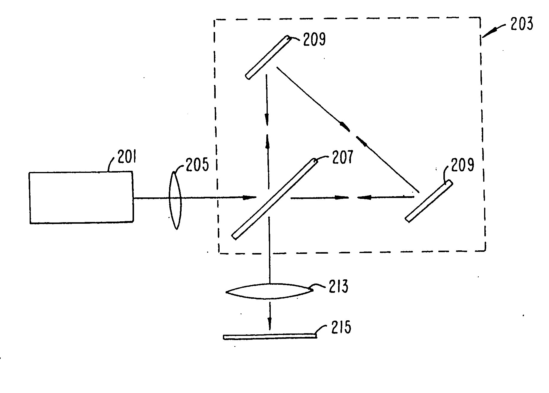
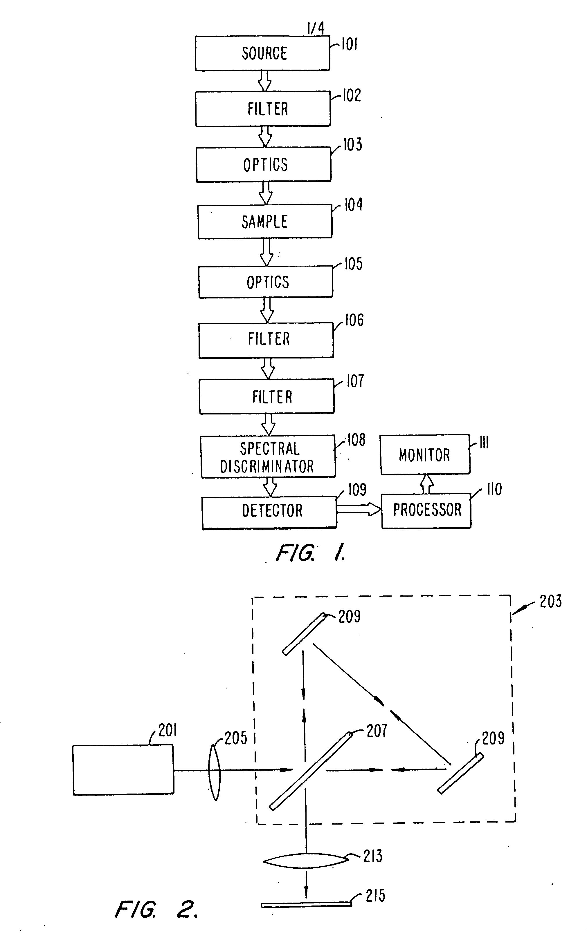
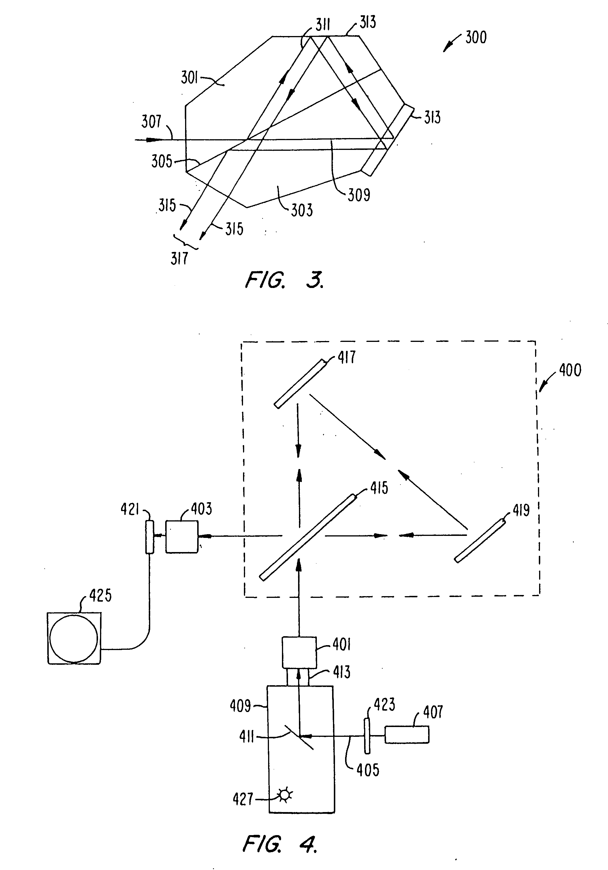
[0017] In another aspect of the invention, the interferometric spectral discriminator includes a polarizing beam splitter. The polarizing beam splitter preferentially reflects one polarization while preferentially transmitting a second polarization. Thus one polarization follows one beam path while a second polarization follows a second beam path. The two polarizations are combined at the focus of the output relay lens. The polarizing beam splitter thereby provides enhanced efficiency while decreasing ghosting within the sample image.
[0018] In another aspect of the invention, a metaphase finder is used to locate areas of interest, thus avoiding wasting analysis time on areas containing only undesirable materials such as cell debris. The metaphase finder utilizes Rayleigh scattering to locate metaphase spreads. The sample plate (e.g., microscope slide) containing the material of interest is illuminated with light of a wavelength determined to preferentially scatter from objects with dimensions of the size of the objects contained within the metaphase spreads (e.g., chromosomes). The intensity of the scattered light versus the location on the sample plate is monitored. This information is used to determine areas of increased scatter, and thus the areas of interest. In order to achieve better discrimination between the metaphase spreads and other matter contained on the sample plate, the plate may be illuminated with light of a second wavelength and the scattered light versus location monitored. The second wavelength is selected such that it does not exhibit increased scattering for the objects of interest and therefore represents background scatter. By subtracting the background scatter from the initial scatter measurements, improved signal to noise is achieved.

Problems solved by technology

This offset results in the fringe density becoming too large to be resolved by the individual pixels of the detector array.

Method used


Image

  • Spectral imaging apparatus and methodology
  • Spectral imaging apparatus and methodology
  • Spectral imaging apparatus and methodology

Examples


Embodiment Construction

[0030] Fluorescence in situ hybridization (FISH) has become an important technique for visualizing DNA sequences in metaphase chromosomes and interphase nuclei. The method is now in routine use in research laboratories for gene localization studies. For example, FISH is used to map genes to specific chromosome regions or to order clones along chromosomes to create or validate clone contigs. More recently, FISH has been applied in clinical situations to detect a variety of chromosome abnormalities.

[0031] Recent efforts in FISH have focused on the development of probe technology. At present, probes are available to a variety of chromosome regions, such as telomeres, or large single-copy genes. These probes have great utility in molecular cytogenetics, with one example being the use of centromere specific probes, derived from repetitive DNA at the centromere of chromosomes, in chromosome enumeration studies. Often these repeat sequences are unique to a specific chromosome and therefor...


PUM


Abstract

A method and apparatus for an improved spectral imaging system is provided. The system is capable of measuring the fluorescence, luminescence, or absorption at selected locations on a sample plate. The emissions detection subassembly can tune to any wavelength within a continuum of wavelengths utilizing an interferometric spectral discriminator. The interferometric spectral discriminator creates an interferogram from which the wavelength spectra for each pixel of the array can be calculated, typically using Fourier transform analysis. In one aspect, the chromatic accuracy of the system is calibrated using a calibration slit placed in the input aperture of the input relay lens but outside of the sample image. The slit is illuminated using a source of known wavelength. The fringe count versus the wavelength of the slit illumination source is monitored and used to calibrate the spectral discriminator. In another aspect, a transparent optic is included in the interferometric spectral discriminator that can be inserted into the beam path whenever a monochrome image of the sample is required. The optic produces a large offset in the legs of the interferometer resulting in the fringe density becoming too large to resolve by the individual pixels of the detector array. In another aspect, the interferometric spectral discriminator includes a polarizing beam splitter. The polarizing beam splitter preferentially reflects one polarization while preferentially transmitting a second polarization, thus achieving improved efficiency while minimizing ghosting. In another aspect, a metaphase finder is used to locate areas of interest. The sample plate containing the material of interest is illuminated with light of a wavelength determined to preferentially scatter from objects the size of the metaphase spreads. The intensity of the scattered light versus the location on the sample plate is monitored and used to locate the areas of interest. Preferably the sample plate is also illuminated by light of a second wavelength which is not preferentially scattered by the objects of interest, thus representing the background scatter. By subtracting the background scatter from the primary scattered light, improved object discrimination is achieved.

Description

CROSS REFERENCE TO RELATED APPLICATIONS [0001] This application is related to commonly assigned U.S. Pat. No. 5,591,981, issued Jan. 7, 1997 and to commonly assigned, co-pending U.S. patent application Ser. No. 08 / 585,303, filed Jan. 11, 1996; 08 / 729,111, filed Oct. 11, 1996; and to an application entitled Fluorescence Imaging Instrument Utilizing FISH, application Ser. No. unassigned, filed Sep. 9, 1997, the complete disclosures of which are incorporated herein by reference for all purposes.FIELD OF THE INVENTION [0002] The present invention relates generally to spectral imaging systems and, more particularly, to a method and apparatus for simplifying the use and calibration of a fluorescence imaging system. BACKGROUND OF THE INVENTION [0003] In the biotechnical field, fluorescent dyes are routinely used as sensitive, non-isotopic labels. These labels are used to identify and locate a variety of cell structures such as specific chromosomes within a DNA sequence. One application, fl...

Claims


Application Information

Patent Timeline
IPC IPC(8): G01B9/02G01J3/45G01N21/64G01J3/28
CPCG01J3/2823G01J2003/2866G01J3/45
Inventor PETTIPIECE, KENNETH J.AMOS, WILLIAM B.
Owner BIO RAD LAB INC
Learn More