
Biosolids digester and process for biosolids production

a biosolids and digester technology, applied in the field of waste processing systems, can solve the problems of limited utility of oxidation ponds, limited reduction of waste sludge quantity, and use of anaerobic digesters, and achieve energy-saving effects

Active Publication Date: 2014-09-16
DVO LICENSING
View PDF80 Cites 9 Cited by
  • Summary
  • Abstract
  • Description
  • Claims
  • Application Information

AI Technical Summary

Benefits of technology

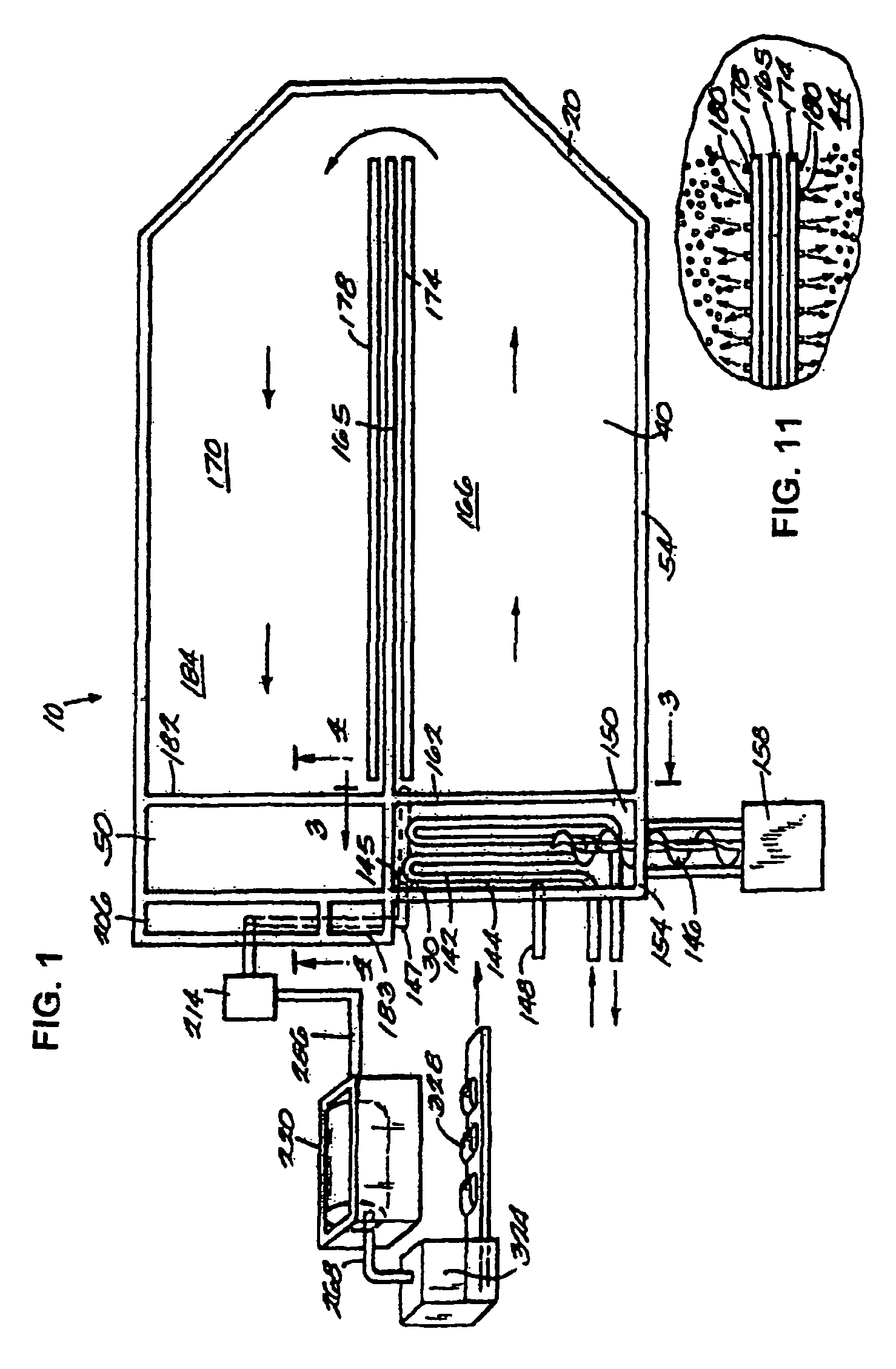
The patent describes a method and apparatus for producing a type of biosolid using heating racks and diffusers. The method involves heating the sludge using heating pipes and convective forces caused by the heated sludge rising near the outer wall. The resulting corkscrew-like flow path allows for efficient mixing of the sludge. This method helps reduce energy costs associated with producing biosolids and allows for capturing excess energy from waste material. Additionally, the method does not require filtering the waste material prior to heating. Overall, this patent provides a more efficient and cost-effective process for producing biosolids.

Problems solved by technology

However, the use of land spreading as a final sludge disposal method may require a well stabilized and pasteurized end product; the concentration of pathogenic organisms in the sludge must be sufficiently low to avoid becoming a health hazard.
The use of oxidation ponds, however, has limited utility, since their operation requires sizable land areas.
Moreover, no significant reduction of the level of pathogens in the sludge and only limited reduction in the quantity of the waste sludge is accomplished by this elementary treatment and disposal method.
In the past, the use of anaerobic digesters has been limited due to high energy demands, which translates into high cost for the end user.
The limited use of anaerobic digestion at temperatures above the mesophilic range may due to higher energy requirements to obtain the higher thermophilic temperature.
Meeting Class A standards will significantly increase the opportunity for biosolids recycling, however, known processes that achieve Class A pathogen densities in biosolids are generally costly, and in most instances, cost prohibitive.

Method used


Image

  • Biosolids digester and process for biosolids production
  • Biosolids digester and process for biosolids production
  • Biosolids digester and process for biosolids production

Examples


Embodiment Construction

Definitions

[0063]The numerical ranges in this disclosure are approximate, and thus may include values outside of the range unless otherwise indicated. Numerical ranges include all values from and including the lower and the upper values, in increments of one unit, provided that there is a separation of at least two units between any lower value and any higher value. As an example, if a compositional, physical or other property, such as, for example, molecular weight, viscosity, melt index, etc., is from 100 to 1,000, it is intended that all individual values, such as 100, 101, 102, etc., and sub ranges, such as 100 to 144, 155 to 170, 197 to 200, etc., are expressly enumerated. For ranges containing values which are less than one or containing fractional numbers greater than one (e.g., 1.1, 1.5, etc.), one unit is considered to be 0.0001, 0.001, 0.01 or 0.1, as appropriate. For ranges containing single digit numbers less than ten (e.g., 1 to 5), one unit is typically considered to b...


PUM

PropertyMeasurementUnit
temperatureaaaaaaaaaa

Abstract

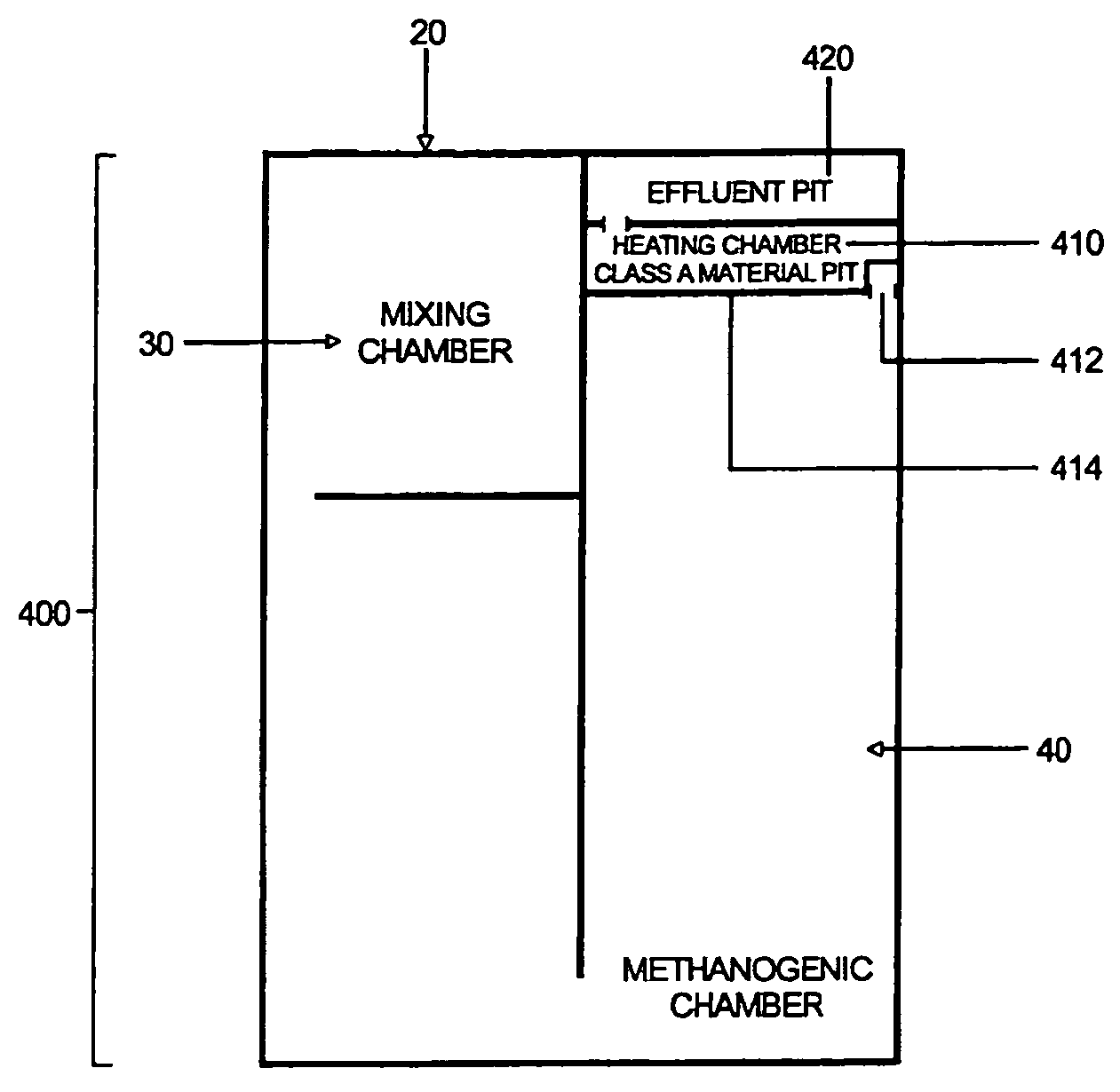
The invention relates to methods and apparatuses for producing Class A biosolids. In yet another embodiment, the invention relates to a method comprising digesting waste material by anaerobic digestion, and yielding Class A biosolids. In still yet another embodiment, the invention relates to a system for anaerobic digestion of waste material to produce Class A biosolids. In still yet another embodiment, the invention relates to a system for anaerobic digestion of waste material comprising a mixing chamber, a digester, a heating pit, and an effluent pit.

Description

CROSS-REFERENCE TO RELATED APPLICATION[0001]This application claims priority to U.S. Provisional Patent Application No. 61 / 264,420 filed Nov. 25, 2009, and is incorporated in its entirety herein by reference.FIELD[0002]The invention relates to waste-processing systems for processing manure, and other waste material. The invention further relates to apparatuses and methods for the production of Class A biosolids. In yet another embodiment, the invention relates to apparatuses and methods for anaerobic digestion of waste material that yield biosolids with fecal coliform densities that are less than 1,000 Most Probable Number (MPN) per gram total solids (dry weight density).BACKGROUND[0003]More than $2 billion is spent annually treating and managing approximately 5.3 million dry metric tons of biosolids from publicly owned wastewater treatment plants in the United States (WEF / U.S. EPA Biosolids Fact Sheet Project, Biosolids: A Short Explanation and Discussion, 2000). Land application o...

Claims


Application Information

Patent Timeline
Patent Type & Authority Patents(United States)
IPC IPC(8): C02F3/30C02F11/04C05F17/00
CPCC05F17/0018C02F11/04C05F17/0027Y02E50/343C05F17/0217Y02W10/23Y02W30/43Y02W30/47C12M21/04C12M29/24C12M41/12C12M41/18Y02P20/145Y02P20/129Y02P20/133C05F17/921C05F17/40C05F17/50Y02E50/30Y02W10/20Y02W30/40
Inventor DVORAK, STEPHEN, W.
Owner DVO LICENSING
Learn More