
Device for a radiation detector and radiation detector with the device

a radiation detector and device technology, applied in the field of devices for radiation detectors and radiation detectors with the devices, can solve the problems of destroying the detector, affecting the detection effect, and being unable to avoid the situation, so as to reduce the number of detectors, and reduce the effect of x-ray fluorescence radiation suppression

Active Publication Date: 2014-09-16
KETEK
View PDF8 Cites 15 Cited by
  • Summary
  • Abstract
  • Description
  • Claims
  • Application Information

AI Technical Summary

Benefits of technology

The patent describes a coating for a radiation detector that can suppress interfering x-ray fluorescence lines. The coating consists of layers of a material (A1) that absorbs the energy of the interfering lines and a material (A2) that emits x-ray fluorescence radiation. The absorption edge of the material A1 should lie below the energy of the interfering lines. The coating can be made with a variety of materials, but it is particularly effective when using materials with an atomic number greater than 10 and a purity greater than 99. The coating can be applied as a cap for the detector or in other ways to suppress x-ray fluorescence radiation in specific regions. Overall, the coating helps to improve the quality and accuracy of x-ray detection.

Problems solved by technology

Sealing of the detector is necessary, for example, if the detector element is cooled and is not operated in a vacuum or under a shielding gas atmosphere, since otherwise air moisture would condense on the cool detector chip and thus destroy the detector.
With a radiation detector, it is often not possible to avoid the situation where the radiation that is to be detected reaches not only the detector element but also the window mount and the protective cap which surround the detector element.
Since on the one hand protective caps and window mounts are usually composed of one or more metals and on the other hand measuring the x-ray fluorescence radiation of metals as samples is a frequent area of use of radiation detectors, such a configuration usually has interfering effects.
Although there is potentially the possibility here to choose the material according to the application such that the secondary radiation lies outside the measuring range, external shieldings nevertheless require additional expenditure and have the effect that the distance between the radiation source and the detector is increased, whereby the detection rate is reduced and the measuring time is prolonged.

Method used


Image

  • Device for a radiation detector and radiation detector with the device
  • Device for a radiation detector and radiation detector with the device
  • Device for a radiation detector and radiation detector with the device

Examples


Embodiment Construction

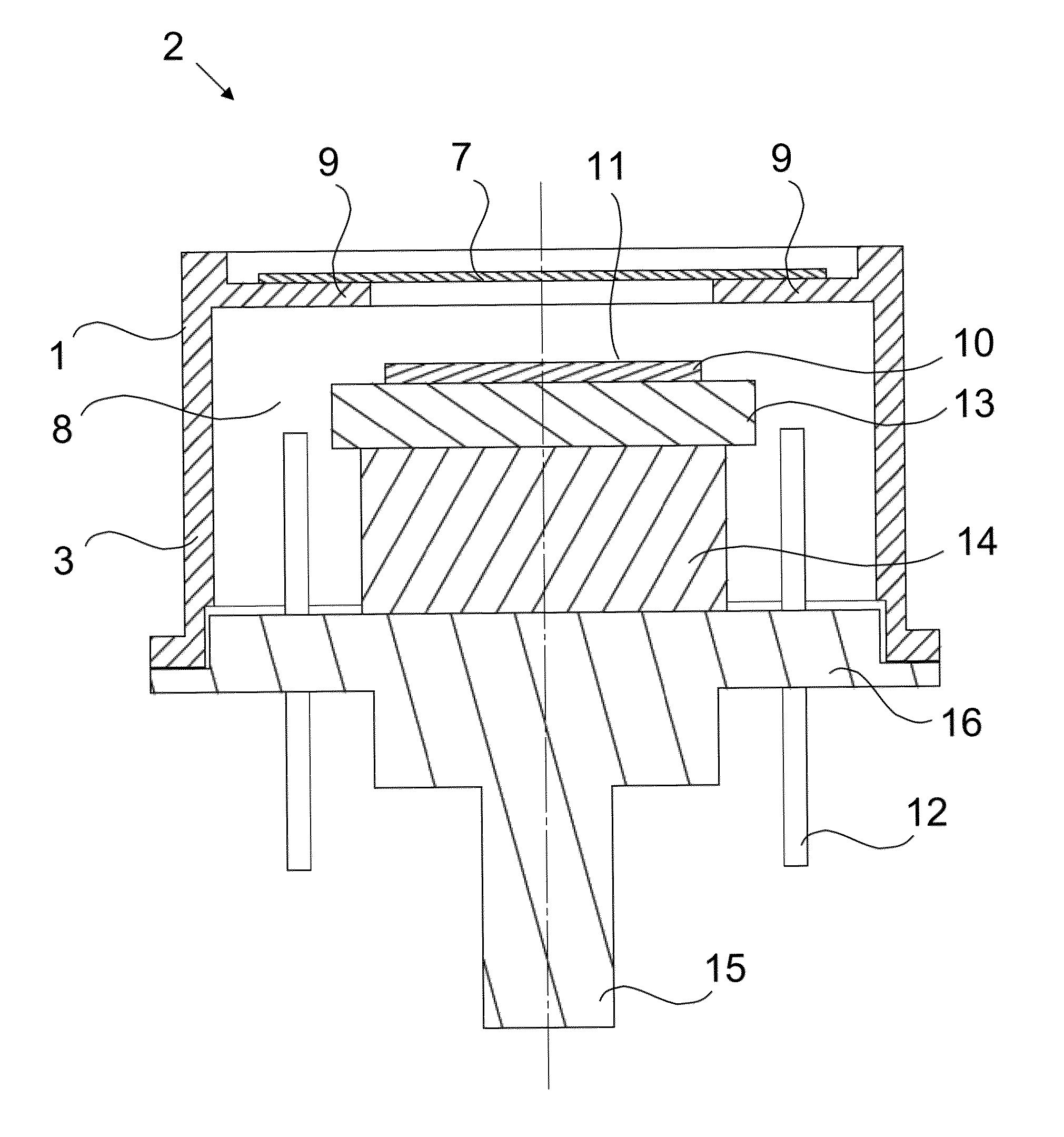
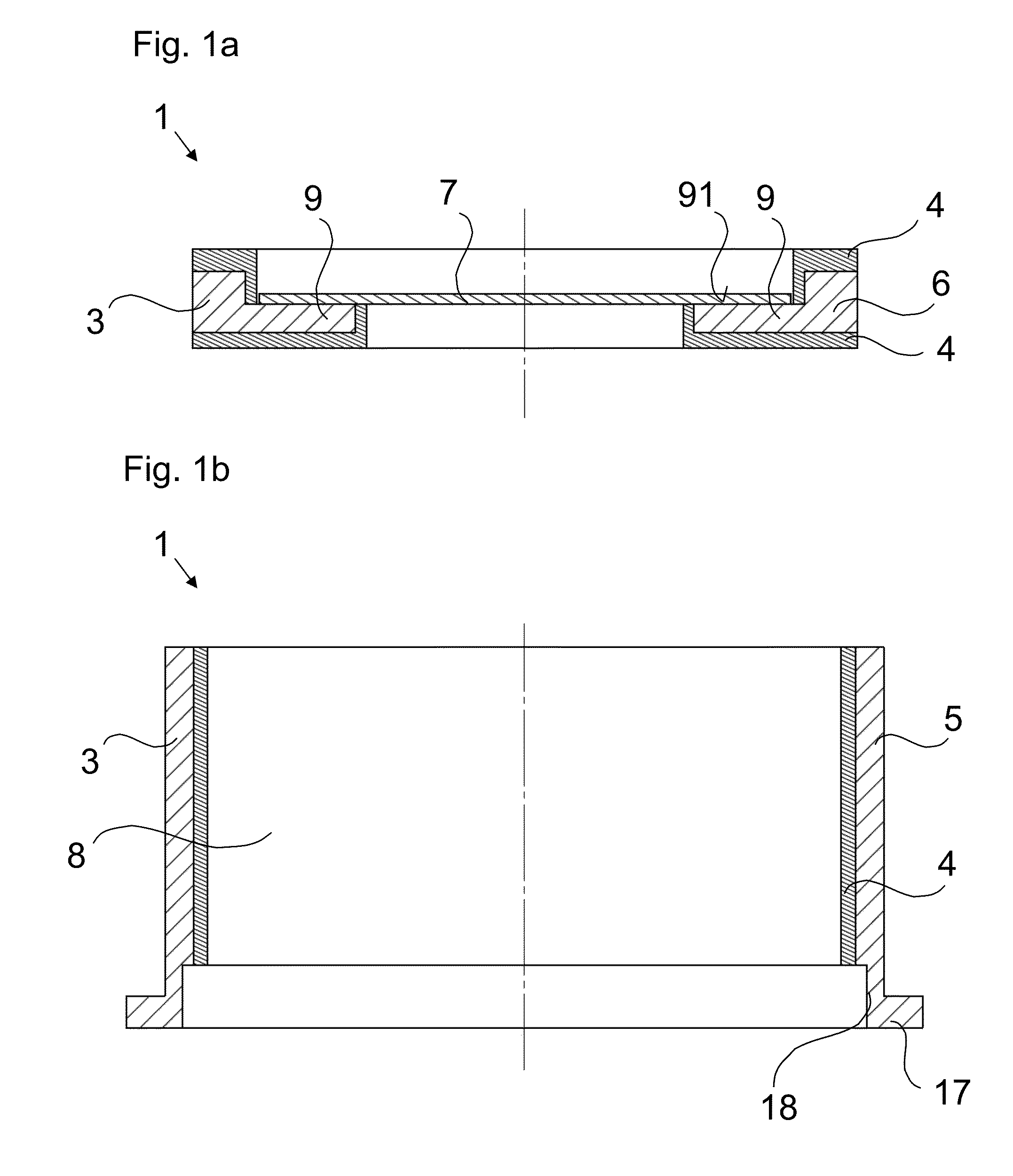
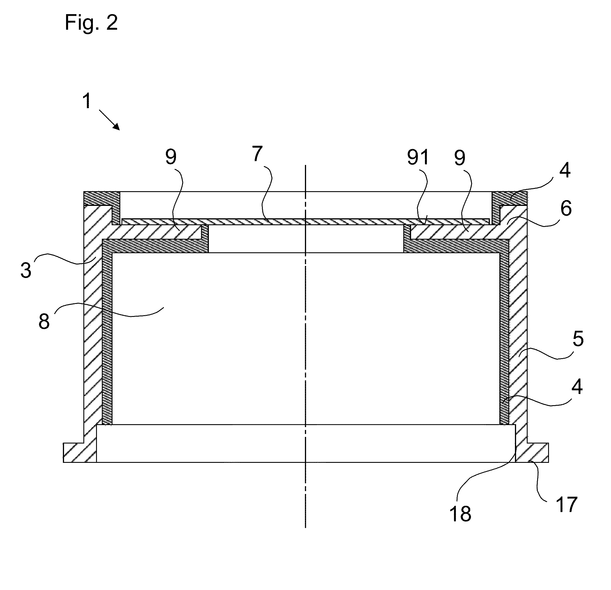
[0049]In FIG. 1a, a device 1 for a radiation detector is represented in a sectional view. The device 1 comprises a main body 3, for example with a circular extent in plan view. Alternatively, the main body 3 may also have a polygonal extent, for example rectangular or square, or an elliptical extent. The main body 3 also comprises a material G or consists of the material G.

[0050]In the exemplary embodiment shown, the device 1 is configured as a window mount 6, the main body 3 having a projection 9, which preferably protrudes inwards into a free space defined by the main body 3. The inside free space may be designed for the primary radiation that is to be detected to pass through the device. The primary radiation may, for example, have an energy of 10 keV.

[0051]In the exemplary embodiment shown, the projection 9 is formed as a peripheral, inwardly protruding projection. Alternatively, the projection 9 may also have a number of inwardly protruding, for example finger-shaped, portions....


PUM

PropertyMeasurementUnit
atomic numberaaaaaaaaaa
pressureaaaaaaaaaa
quantum efficiencyaaaaaaaaaa

Abstract

A device for a radiation detector includes a main body, which includes a material G and is at least partially provided with a coating. The coating has at least a first layer with a material A1. The material G of the main body can be excited by a primary radiation impinging on the coating, so that an x-ray fluorescence radiation is produced with an x-ray fluorescence spectrum, which has a maximum MG at an energy EG. Furthermore, at an energy E1, the material A1 has an absorption edge. In this case, the material A1 is chosen such that the relationships E1<EG and EG−E1≦̸4 keV apply. Also specified is a radiation detector, which has the device and a detector element, which is suitable for the detection of the primary radiation.

Description

[0001]This application claims the benefit of U.S. Provisional Application No. 61 / 521,550, filed on Aug. 9, 2011, and German Patent Application No. 10 2011 109 822.8, filed Aug. 9, 2011, each of which is incorporated herein by reference in its entirety.TECHNICAL FIELD[0002]A device for a radiation detector is specified. Also specified is a radiation detector which has such a device.[0003]Radiation detectors often have a protective cap, which is intended to protect a signal-generating detector element and possibly further elements of the radiation detector from external mechanical damage and often to serve at the same time as a mount for a radiation entrance window. Such a protective cap with a window mount and a window makes it possible for the detector to be hermetically sealed. Sealing of the detector is necessary, for example, if the detector element is cooled and is not operated in a vacuum or under a shielding gas atmosphere, since otherwise air moisture would condense on the co...

Claims


Application Information

Patent Timeline
Patent Type & Authority Patents(United States)
IPC IPC(8): G01T1/20G01N23/223G01T7/00
CPCG01T7/00G01N23/223
Inventor EGGERT, TOBIAS
Owner KETEK
Learn More