Work vehicle

a technology for working vehicles and vehicles, applied in the direction of machines/engines, mechanical equipment, transportation and packaging, etc., can solve the problems of increasing engine vibration, increasing the combined weight of devices, and increasing the center of gravity of engines, so as to prevent the unnecessary increase in the length of the entire pipe uni

Active Publication Date: 2014-10-07
KOMATSU LTD
View PDF11 Cites 26 Cited by
  • Summary
  • Abstract
  • Description
  • Claims
  • Application Information

AI Technical Summary

Benefits of technology

[0018]Accordingly in the present invention, the pipe unit extends from the exhaust part of the engine past the diesel particulate filtering device, and an end part thereof is coupled to the exhaust gas inlet of the diesel particulate filtering device from the rear. The pipe unit can be made sufficiently long with such a configuration. As a result, a relatively long flexible pipe part can be formed in the extending part that extends from the exhaust part of the engine past the diesel particulate filtering device, and the difference in the vibrations of the engine and the diesel particulate filtering device can be sufficiently absorbed. Further, the installation error between the engine and the diesel particulate collection and filtering device can be sufficiently absorbed by the same reason.
[0036]The length of the extending part of the pipe unit is secured while an unnecessary increase in the length of the entire pipe unit can be prevented.

Problems solved by technology

However, when the diesel particulate filtering device is mounted on the engine in addition to the nitrogen oxide reduction catalytic converter, the combined weight of the devices becomes very large and the center of gravity of the engine becomes higher.
As a result, engine vibration increases which is undesirable.
However, the flexible pipe described in Japanese Laid-open Patent Publication No. 2012-97413 is not able to sufficiently absorb the difference in both of the vibrations.
A pipe connecting the exhaust part of the engine and the diesel particulate filtering device is desirably short in consideration of costs and in the space occupied by the members.
As a result, the aforementioned difference in the vibration from the engine and the vibration from the exhaust gas post-processing device cannot be sufficiently absorbed.
Further, an installation error is produced when installing the engine and the exhaust gas post-processing device in the configuration of Japanese Laid-open Patent Publication No. 2012-97413 since both devices are supported separately on the vehicle frame.
However, sufficiently absorbing the installation error between the engine side and the exhaust gas post-processing side with the flexible pipe of Japanese Laid-open Patent Publication No. 2012-97413 is difficult due to the same reason as described above.
As described above, the entire length of the conventional flexible pipe that connects the engine and the diesel particulate filtering device is short and thus a flexible portion cannot be sufficiently secured.
Further, the installation error between the engine and the diesel particulate collection and filtering device can be sufficiently absorbed by the same reason.
As a result, an installation error between the engine side and the diesel particulate filtering device side can be absorbed in the coupling parts of both pipes.
Since the spherical joints are provided at both ends of the upstream side pipe, an angle error that is produced during the installation of the engine and the diesel particulate filtering device can be easily absorbed.
In this case, the mass of the entire exhaust gas post-processing increases and the vibration becomes very large.
However, under the condition in which the front end of the pipe unit is located between the nitrogen oxide reduction catalytic converter and the diesel particulate filtering device as in the work vehicle according to the eighth aspect, the length of the extending part, that is, the flexible pipe part, of the pipe unit cannot be secured sufficiently.

Method used


Image

  • Work vehicle
  • Work vehicle
  • Work vehicle

Examples


Embodiment Construction

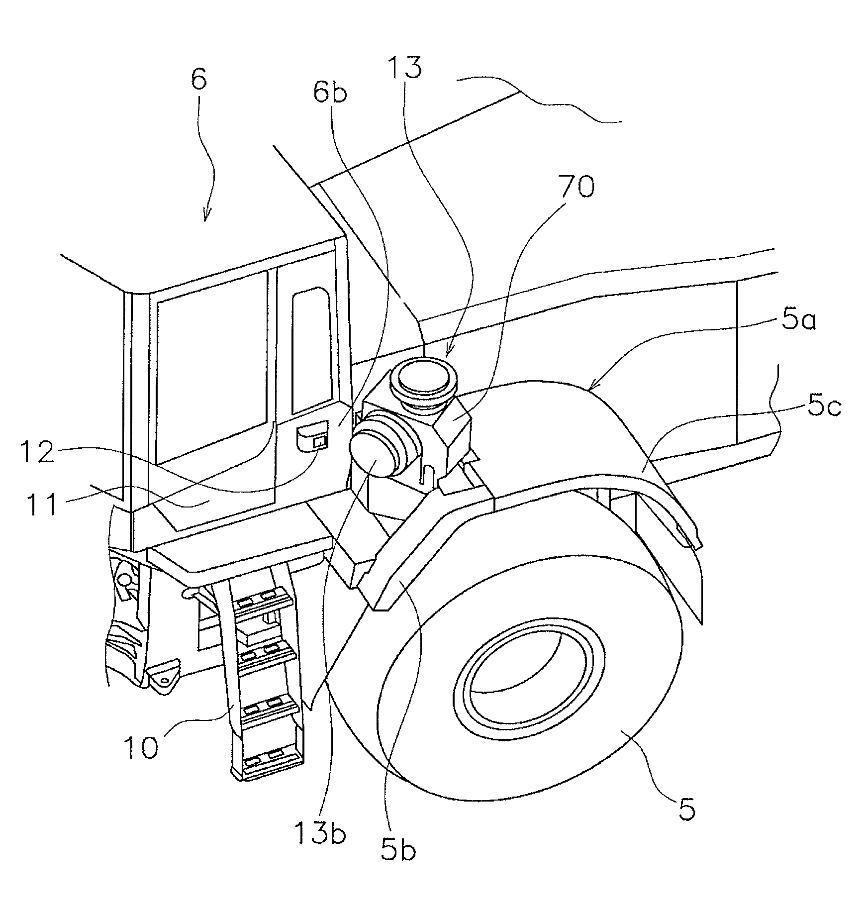
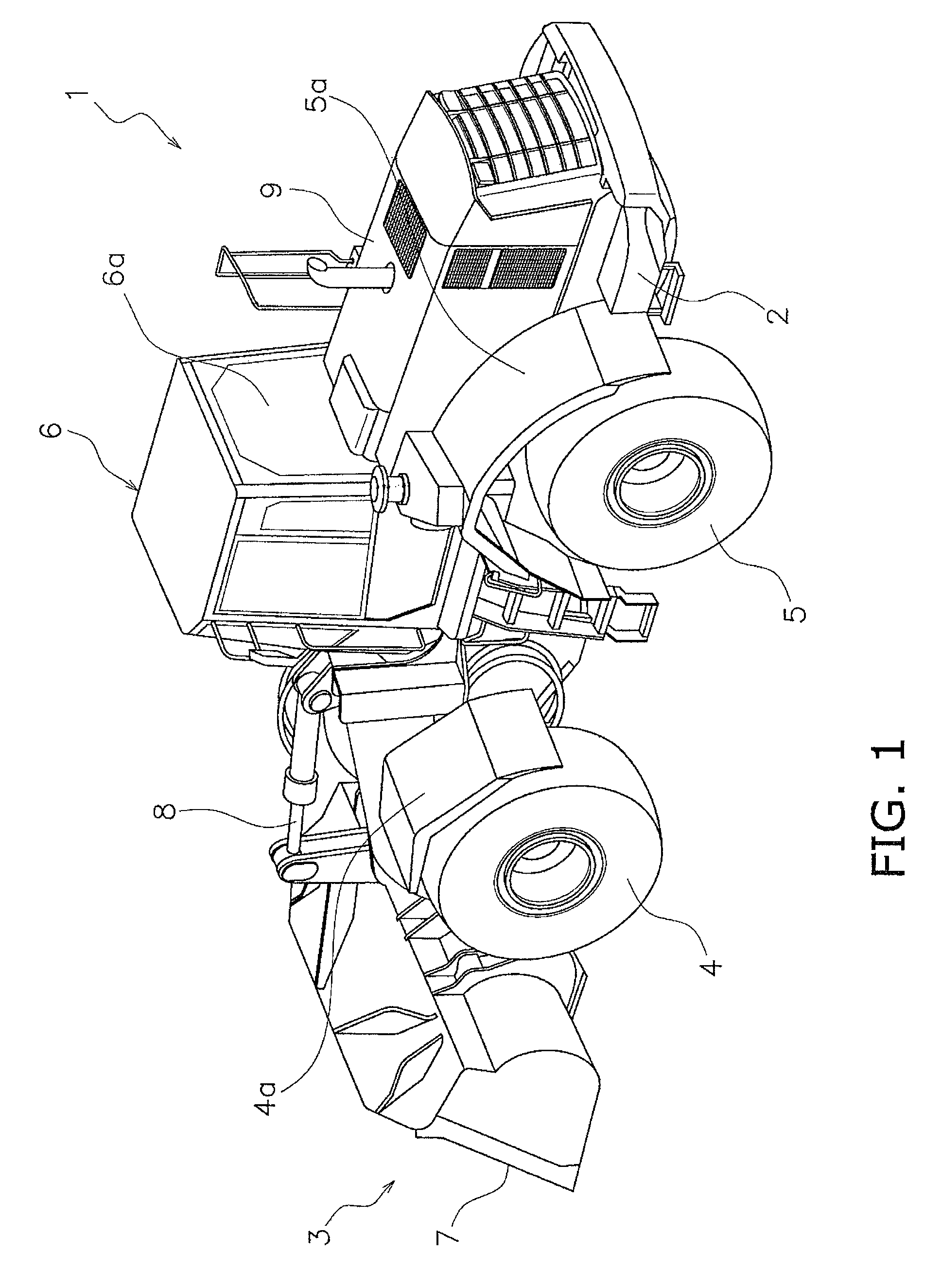
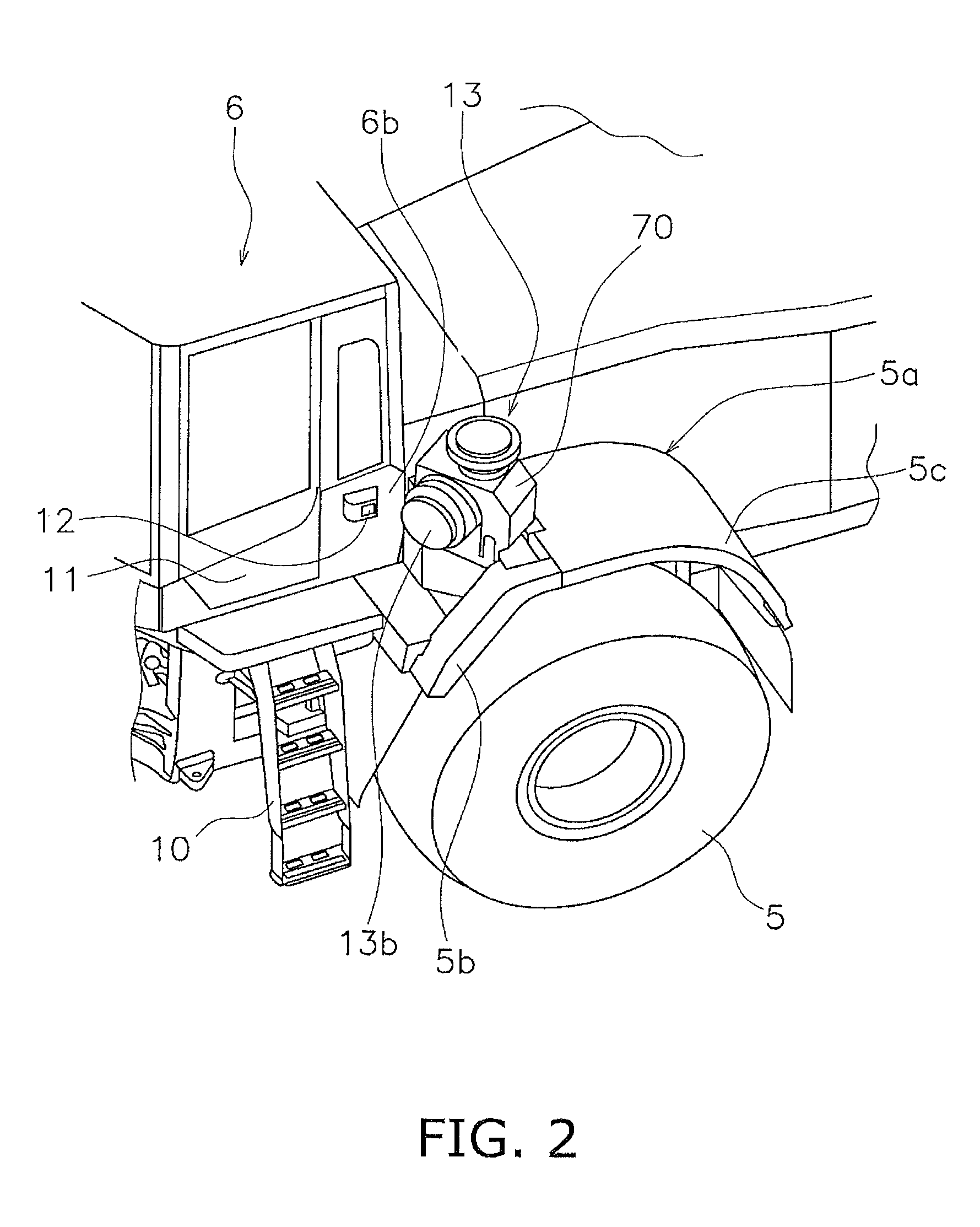
[0051]FIG. 1 illustrates an external perspective view of a wheel loader according to an embodiment of the work vehicle of the present invention. FIG. 2 illustrates a portion of the wheel loader on the left side of the cab.

[0052]In the following explanation, “front” refers to the front of the vehicle and “rear” refers to the rear of the vehicle. “Left” and “right” refer respectively to the left and right of the vehicle looking toward the front of the vehicle.

Overall Configuration

[0053]A wheel loader 1 includes a vehicle body frame 2, working equipment 3, front wheels 4, rear wheels 5, and a cab 6. The wheel loader 1 is capable of traveling due to the rotation of the front wheels 4 and the rear wheels 5, and desired work can be conducted using the working equipment 3.

[0054]The vehicle body frame 2 includes a front body part and a rear body part, and the front body part and the rear body part are connected to each other to allow for pivoting in the crosswise direction. The working equi...


PUM


Abstract

A wheel loader includes a vehicle frame, an engine, a supporting mechanism, a diesel articulate filtering device, and a connecting pipe. The engine is mounted on the vehicle frame, and the supporting mechanism is fixed to the vehicle frame. The diesel particulate filtering device is mounted on the supporting mechanism above the engine and has an exhaust gas inlet facing the rear. An exhaust upstream side end part of the connecting pipe is coupled to an exhaust part of the engine, and an exhaust downstream side end part of the connecting pipe is connected to an exhaust gas inlet of the diesel particulate filtering device from the rear. The connecting pipe includes an extending part that is disposed below the diesel particulate filtering device and extends rearward of the diesel particulate filtering device from the exhaust upstream side end part, and a flexible pipe part provided in the extending part.

Description

CROSS-REFERENCE TO RELATED APPLICATIONS[0001]This application is a U.S. National stage application of International Application No. PCT / JP2012 / 082135, filed on Dec. 12, 2012. This U.S. National stage application claims priority under 35 U.S.C. §119(a) to Japanese Patent Application No. 2012-237065, filed in Japan on Oct. 26, 2012, the entire contents of which are hereby incorporated herein by reference.BACKGROUND[0002]1. Field of the Invention[0003]The present invention relates to a work vehicle and in particular to a work vehicle equipped with an exhaust gas post-processing device above an engine.[0004]2. Background Information[0005]An exhaust gas post-processing device is mounted on a work vehicle. The exhaust gas post-processing device includes a diesel particulate filtering device that collects and removes particulate matter of soot and the like included in the diesel engine exhaust. The diesel particulate filtering device is mounted in a row with an air cleaner on an upper part...

Claims


Application Information

Patent Timeline
Patent Type & Authority Patents(United States)
IPC IPC(8): B60K13/04
CPCB60K13/04F01N13/1855B60Y2200/415F01N2340/04F01N13/1816F01N13/1811F01N3/021F01N13/1822F01N2470/18F01N2590/08
Inventor HAYASHI, DAISUKEMATSUYAMA, NOBUO
Owner KOMATSU LTD
Why Eureka
Try Eureka