Collimator device and laser light source

a collimator and laser light source technology, applied in the field of collimator devices and laser light sources, can solve the problems of chromatic aberration and affect processing accuracy, and achieve the effect of reducing the wavelength-by-wavelength differences of focal positions and reducing the wavelength-by-wavelength differences of positions

Inactive Publication Date: 2014-10-07
SUMITOMO ELECTRIC IND LTD
View PDF4 Cites 1 Cited by
  • Summary
  • Abstract
  • Description
  • Claims
  • Application Information

AI Technical Summary

Benefits of technology

[0007]The present invention has been accomplished in order to solve the problem as described above and it is an object of the present invention to provide a collimator device capable of achieving further reduction in the wavelength-dependent position differences of the beam waists where plane waves are formed (variations of beam waist positions depending upon the wavelengths in polychromatic light), in collimating the polychromatic light with a wide spectrum width, and a laser light source capable of reducing the focal length differences depending upon the wavelengths in the polychromatic light.
[0010]Particularly, in the laser light source of the second aspect, a distance between the position of entrance of the laser beam and a center position of the collimating lens is adjusted in a relation of the position of entrance of the laser beam and an adjustment position of the collimating lens, against a variation range of beam waist positions formed through the collimating lens (or a difference between a wavelength-dependent maximum variation and a wavelength-dependent minimum variation) (cf. FIG. 7). The adjustment position is defined by a deviation amount relative to a focal length of the collimating lens at a reference wavelength component in the laser beam, of the distance between the position of entrance of the laser beam and the center position of the collimating lens. The variation range is defined by a difference between a maximum and a minimum of variations relative to a beam waist position of the reference wavelength component formed through the collimating lens, of beam waist positions differing depending upon wavelength components of the laser beam. The distance between the position of entrance of the laser beam and the center position of the collimating lens is adjusted so that the adjustment position falls between a position where the variation range becomes minimum and a position where the variation range becomes sub-peak. When the distance between the position of entrance of the laser beam (light exit end face of the optical fiber) and the center position of the collimating lens is set in this manner, the wavelength-dependent variation of beam waist positions where plane waves are formed, is reduced even with the different wavelength components. Therefore, it becomes feasible to reduce the wavelength-by-wavelength differences of positions where plane waves are formed when the polychromatic light is collimated into parallel light and to also reduce the wavelength-by-wavelength differences of focal positions after focused by the condensing lens.

Problems solved by technology

In microfabrication such as laser processing in the thickness direction of a thin substrate requiring accuracy of depth, chromatic aberration can affect processing accuracy.

Method used


Image

  • Collimator device and laser light source
  • Collimator device and laser light source
  • Collimator device and laser light source

Examples


first embodiment

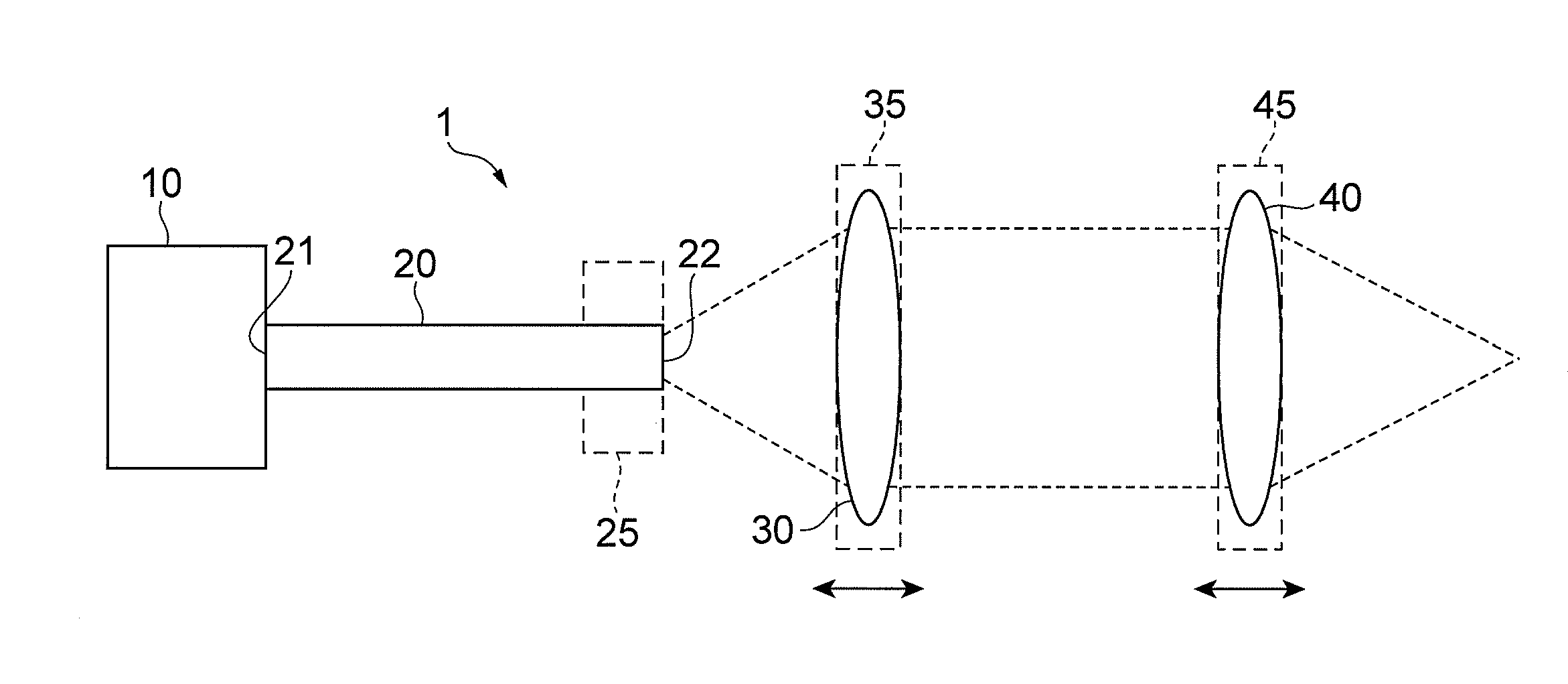
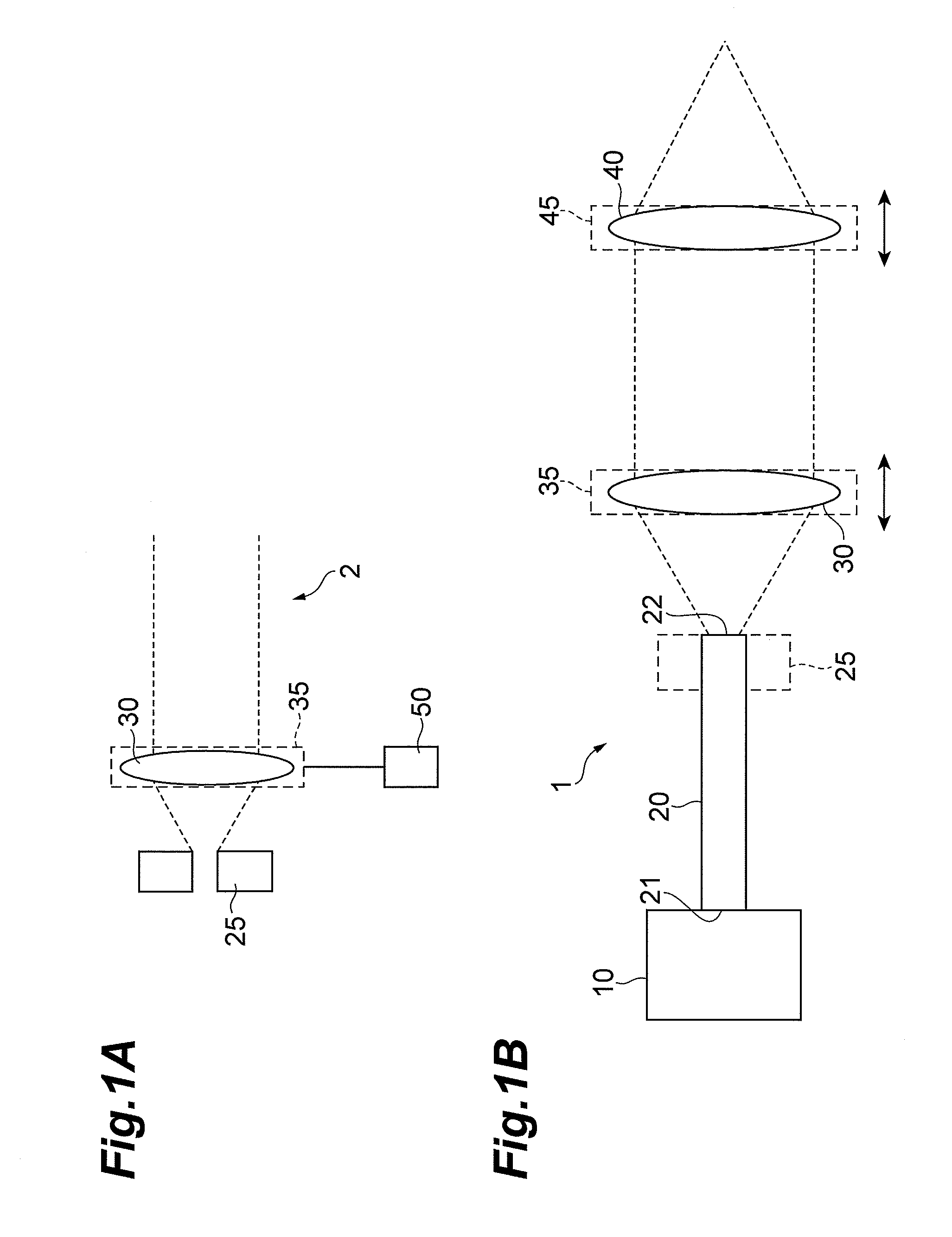
[0025]FIGS. 1A and 1B are schematic configuration diagrams of a collimator device 2 and a laser light source 1 according to the first embodiment. The collimator device 2 in FIG. 1A is composed of a laser entrance unit 25 to set a position of emission of a laser beam, a collimating lens 30, a collimating lens setup unit 35 to fix the collimating lens 30, and a position adjustment unit 50 to adjust a position of the laser entrance unit in order to adjust a spacing between a laser exit position (fiber exit end face) 22 of the laser entrance unit 25 and a position of the collimating lens 30. The position adjustment unit 50 may be arranged so as to be able to adjust a position of the collimating lens setup unit 35. The laser light source 1 in FIG. 1B is constructed including a light source 10, an optical fiber 20, the laser entrance unit 25 to fix the end face 22, the collimating lens 30, the collimating lens setup unit 35 to fix the collimating lens 30, a condensing lens 40, and a conde...

second embodiment

[0042]FIG. 9 is a schematic configuration diagram of a laser light source 100 according to the second embodiment. This laser light source 100 according to the second embodiment includes the configuration of the laser light source 1 according to the first embodiment shown in FIG. 1B, and is further provided with a pinhole mask 26 installed at the exit position of the laser beam or at the exit end face 22 of the optical fiber 20 in which single-mode light propagates. A pinhole 260 is formed in the pinhole mask 26 and the size (aperture diameter) of the pinhole 260 is approximately equal to or 10% smaller than the mode field diameter of the optical fiber 20 for the shortest wavelength component out of wavelength components of the polychromatic light emitted from the polychromatic light source 10. The pinhole mask 26 is preferably one having the thickness as small as possible, about 100 μm or less. When the pinhole mask 26 is thicker than it, the sectional shape of the pinhole 260 is pr...


PUM

PropertyMeasurementUnit
distanceaaaaaaaaaa
spectrum widthaaaaaaaaaa
wavelengthaaaaaaaaaa

Abstract

The present invention relates to a laser light source and others for decreasing wavelength-by-wavelength differences of focal positions of focused components in collimating and then focusing polychromatic light with a wide spectrum width. The laser light source includes a collimator device, in which relative positions of emergence of a laser beam emitted from a polychromatic light source and a collimating lens composed of an achromatic lens can be adjusted at a 10 μm level or less.

Description

CROSS-REFERENCE TO RELATED APPLICATION[0001]This application is based upon and claims the benefit of priorities from U.S. Provisional Application No. 61 / 616,109, filed on Mar. 27, 2012 and Japanese Patent Application No. 2011-189126, filed on Aug. 31, 2011, the entire contents of which are incorporated herein by reference.BACKGROUND OF THE INVENTION[0002]1. Field of the Invention[0003]The present invention relates to a collimator device for collimating incoming light with a wide spectrum width and a laser light source for realizing irradiation with laser light obtained by collimating and then focusing incoming light with a wide spectrum width.[0004]2. Related Background of the Invention[0005]Processing with a laser beam is carried out using a configuration wherein a laser beam emitted to diverge from an end face of an optical fiber is collimated and thereafter the collimated laser beam is focused by a condensing lens to be concentrated at a point of a workpiece. When the laser beam ...

Claims


Application Information

Patent Timeline
Patent Type & Authority Patents(United States)
IPC IPC(8): G02B27/30B23K26/06
CPCG02B27/30B23K26/0648B23K26/0665B23K26/066
Inventor NAGANO, SHIGEHIROKAKUI, MOTOKI
Owner SUMITOMO ELECTRIC IND LTD
Why Eureka
Try Eureka