
Lateral drilling tool and method from vertical bore hole

a drilling tool and lateral technology, applied in the direction of directional drilling, borehole/well accessories, artificial islands, etc., can solve the problems of reducing the intended penetration force, unable to achieve effective, and unusable Vaughn design, so as to reduce equipment requirements and associated costs, reduce the length of the lateral run, and save time.

Inactive Publication Date: 2014-10-21
PARMENTIER PAUL PIERRE
View PDF20 Cites 2 Cited by
  • Summary
  • Abstract
  • Description
  • Claims
  • Application Information

AI Technical Summary

Benefits of technology

The patent aim is to find a way to insert longer pipe segments in vertical bore holes and in soft soils like clay. This has two major benefits: it allows for a higher density of holes in the final segmented total pipe length, improving fluid flow, and it also allows for a more effective penetrating leading end of the segmented pipe. Additionally, it means that we can dust off the cobwebs and start over, using a new method to achieve faster and less expensive results.

Problems solved by technology

In softer soil such as clay or silt, where steady gripping is not possible, this requirement for gripping of rock for bracing would make this Vaughn design unusable or at least very impractical.
Under the intent of penetrating softer soil, anchoring the tool to the side of the bore hole cannot be achieved effectively, and the wedge's upward thrusting energy would be commensurately lost to downward slide of the tool, reducing the intended force of penetration.
Besides the loss of penetrating power, this downward push under the Vaughn design in soft soil would also result in vertical displacement of the tool due to unsecure anchoring.
This vertical displacement would cause an inability to align each successive pipe segment to the previously installed pipe segment.
This system uses a rotating bit to drill the lateral bore and is complex.
This system also uses a drilling bit and is a complex device.

Method used


Image

  • Lateral drilling tool and method from vertical bore hole
  • Lateral drilling tool and method from vertical bore hole
  • Lateral drilling tool and method from vertical bore hole

Examples


Embodiment Construction

)

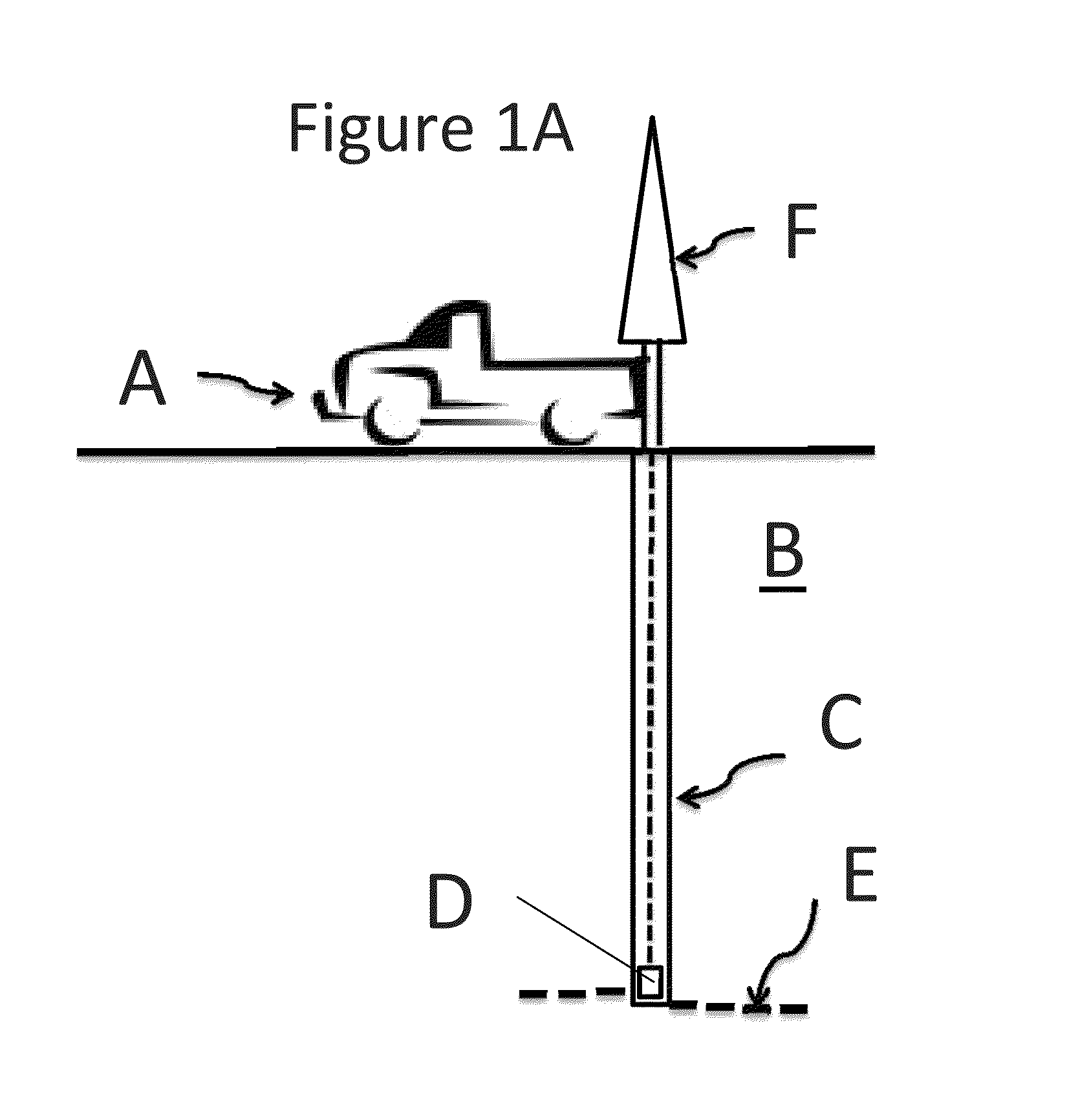
[0062]As shown in FIG. 1A, in general, there is a set up or system for drilling vertical bore holes and lateral bore holes there from.

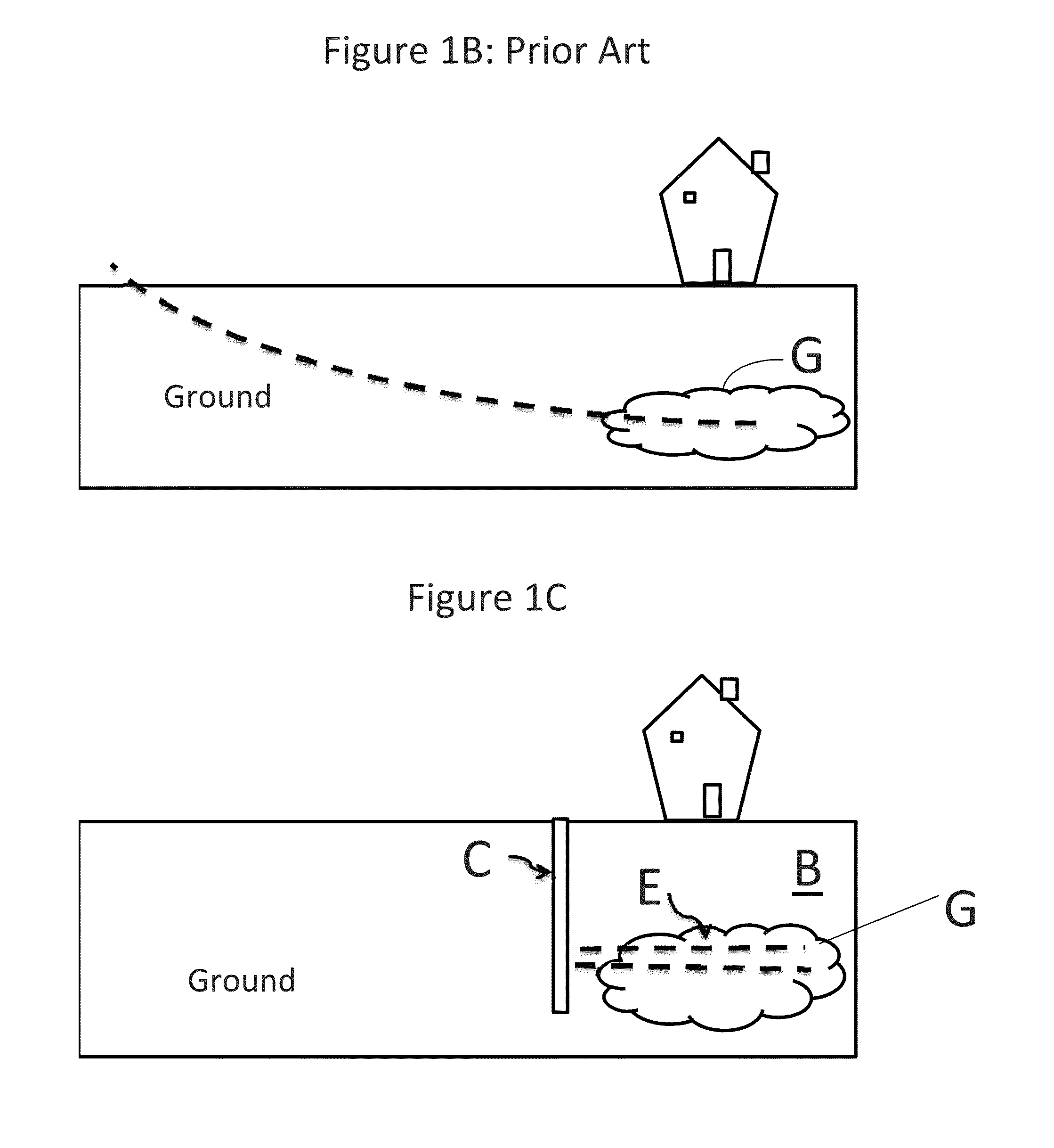
[0063]A drilling rig A includes a truck and a vertical drilling tool or rig F to create a vertical or substantially vertical bore hole C in ground B. In the vertical bore hole there is a radial drilling tool D for drilling transversely to the vertical bore hole, e.g., horizontally or substantially horizontally and to lay pipe segments or sections E extending in such transverse or horizontal direction, preferably normal to an axis of the vertical bore hole.

[0064]The vertical bore hole is initially drilled using conventional drilling methods. Lateral drilling is then conducted using the tool D inside the vertical bore hole. If the lateral drilling tool D is to be used for one-time access (e.g., for chemical injection or mechanical fracturing of the soil), then the tool D is inserted in the bore hole right after vertical drilling and thus pipe segment i...


PUM


Abstract

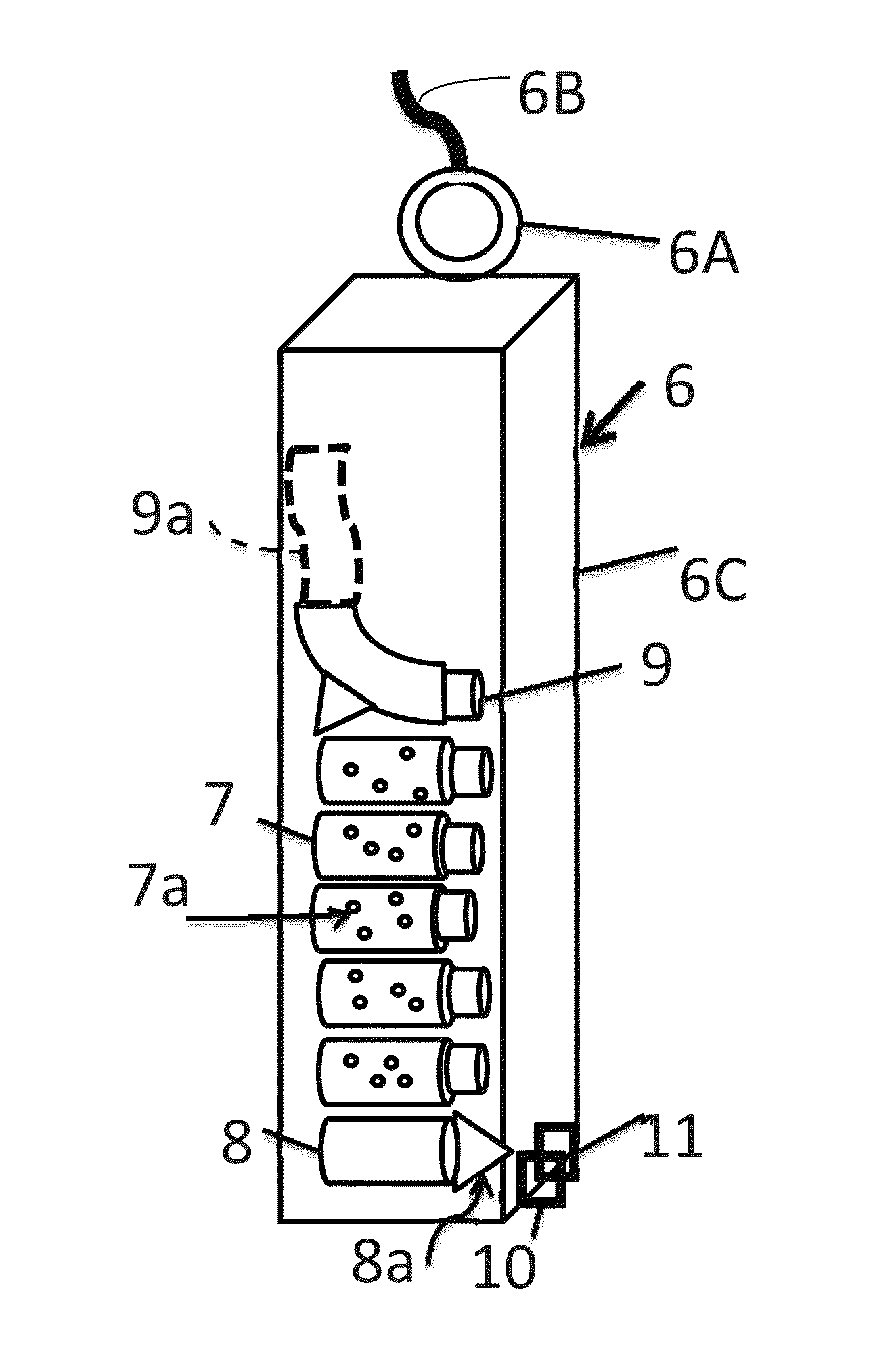
A lateral drilling system includes a device for drilling a first bore hole, preferably vertical or substantially vertical, and including a tool for boring a second bore hole in a direction transverse, preferably normal or substantially normal, to the first bore hole. The vertical boring tool may be any vertical boring device. A casing for the first bore hole may be used. The tool for boring the second bore hole includes a pipe launching section and a pipe receiving section. There is also a removable rack for holding a supply of pipe segments, each segment having a lead end of reduced diameter for fitting into a tail end of a preceding pipe segment, so that the segments form a conduit which may be used to treat surrounding ground. The tool includes a frame for holding the pipe receiving section, pipe launching section and pipe launching mechanism. The pipe launching mechanism includes a pushing arm and a power source to push each pipe segment one by one into the ground. A stabilizing mechanism may also be used to stabilize the device's frame.

Description

CROSS REFERENCE TO RELATED APPLICATION(S)[0001]This application claims priority from U.S. Provisional Patent Application Ser. No. 61 / 357,092, filed Jun. 22, 2010, and which is incorporated by reference herein.BACKGROUND OF THE INVENTION[0002]1. Field of the Invention[0003]The present invention relates to a lateral drilling system, a lateral drilling tool and a method for drilling laterally from a vertical bore hole in the ground to bore lateral holes, termed herein as “roots” or “lateral roots.”[0004]2. Description of the Related Art[0005]There have been many attempts to design a device and method for laterally drilling from a vertical bore hole. U.S. Pat. No. 3,301,337 to Vaughn et al, issued Jan. 31, 1967, describes an apparatus for completing a well by pushing a plurality of conduit sections laterally with respect to a bore hole in a formation. This apparatus uses a hydraulic piston activated with a sucker rod with a ten-foot long stroke that operates a twelve-degree wedge to ins...

Claims


Application Information

Patent Timeline
Patent Type & Authority Patents(United States)
IPC IPC(8): E21B49/06
CPCE21B49/06E21B7/068
Inventor PARMENTIER, PAUL, PIERRE
Owner PARMENTIER PAUL PIERRE
Learn More