Air battery system
a battery system and air technology, applied in the field of air battery systems, can solve the problems of increasing internal resistance, shortening liquid electrolyte, and reducing the service life of secondary cells, and achieve the effect of restricting internal resistan
- Summary
- Abstract
- Description
- Claims
- Application Information
AI Technical Summary
Benefits of technology
Problems solved by technology
Method used
Image
Examples
example 1
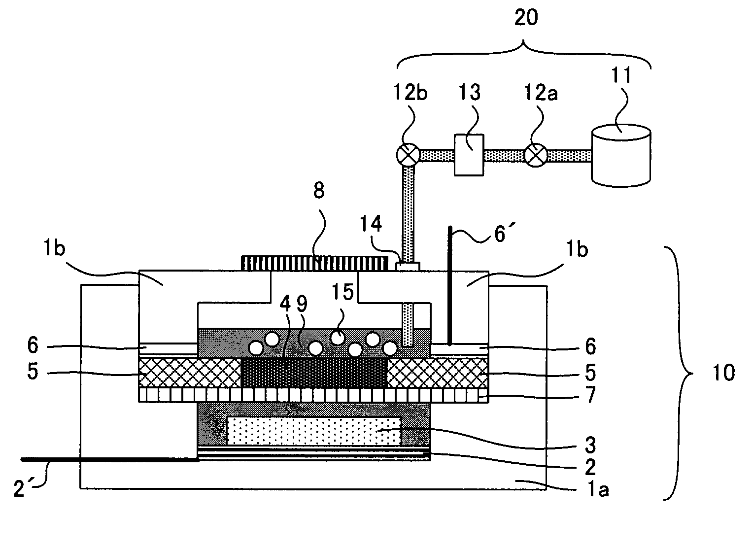
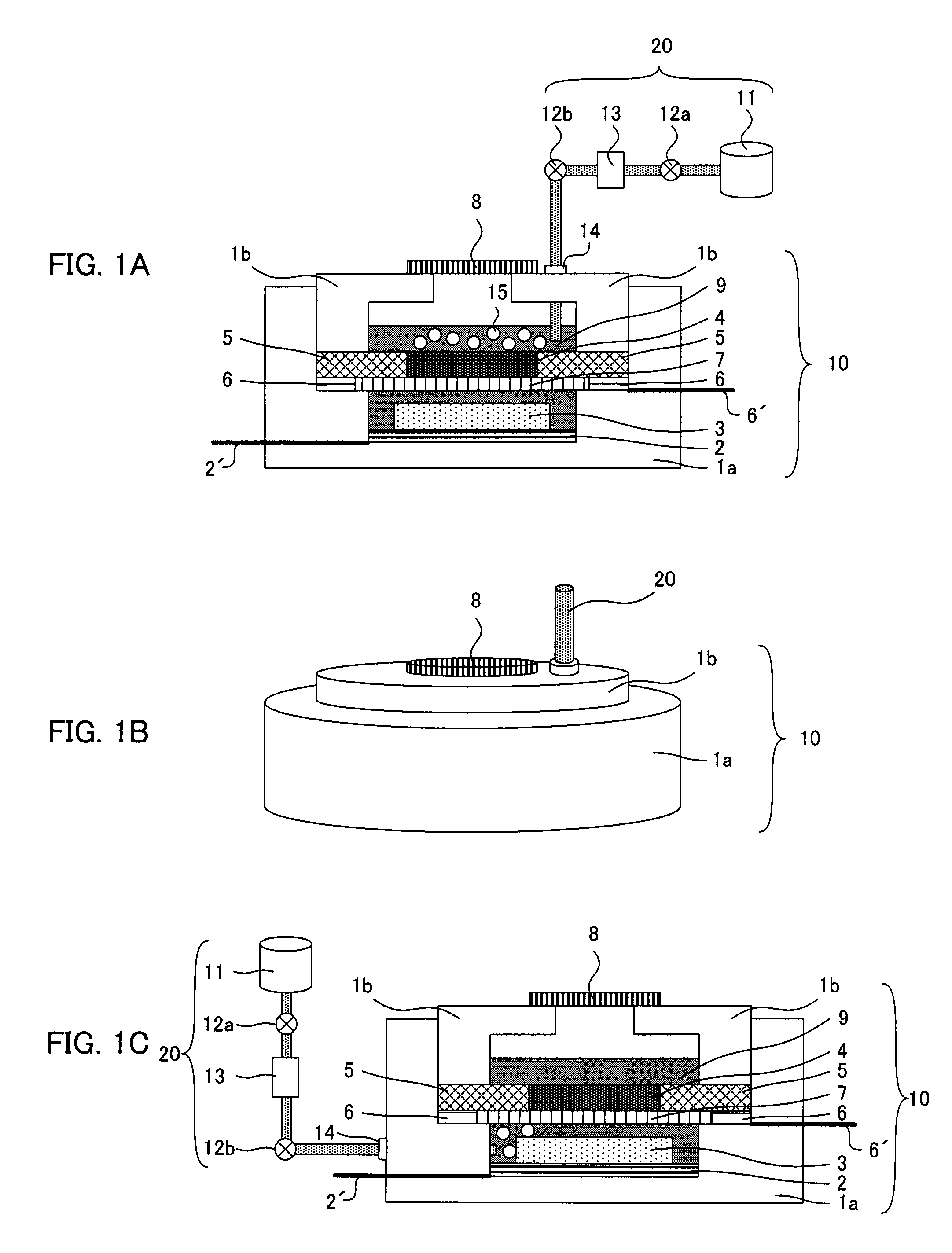
[0108]The present example will be explained with reference to FIG. 1A. Assembling of the following cell was conducted in an argon box. First, an air cathode current collector 2 was provided in the inside of a lower insulating case 1a, and the air cathode current collector 2 was jointed to an anode lead 2′. The anode lead 2′ ran through the lower insulating case 1a and penetrated to the outside. Next, an anode layer 3 was provided on the air cathode current collector 2. Then, an air cathode current collector 6 was provided in the middle of the lower insulating case 1a, and the air cathode current collector 6 was jointed to an air cathode lead 6′. The air cathode lead 6′ ran through the lower insulating case 1a and penetrated to the outside. Further next, a separator 7 was provided in the upper middle of the lower insulating case 1a, and an air cathode mesh 5 and an air cathode layer 4 were provided thereon.
[0109]The inner side of the lower insulating case 1a was threaded and could be...
example 2
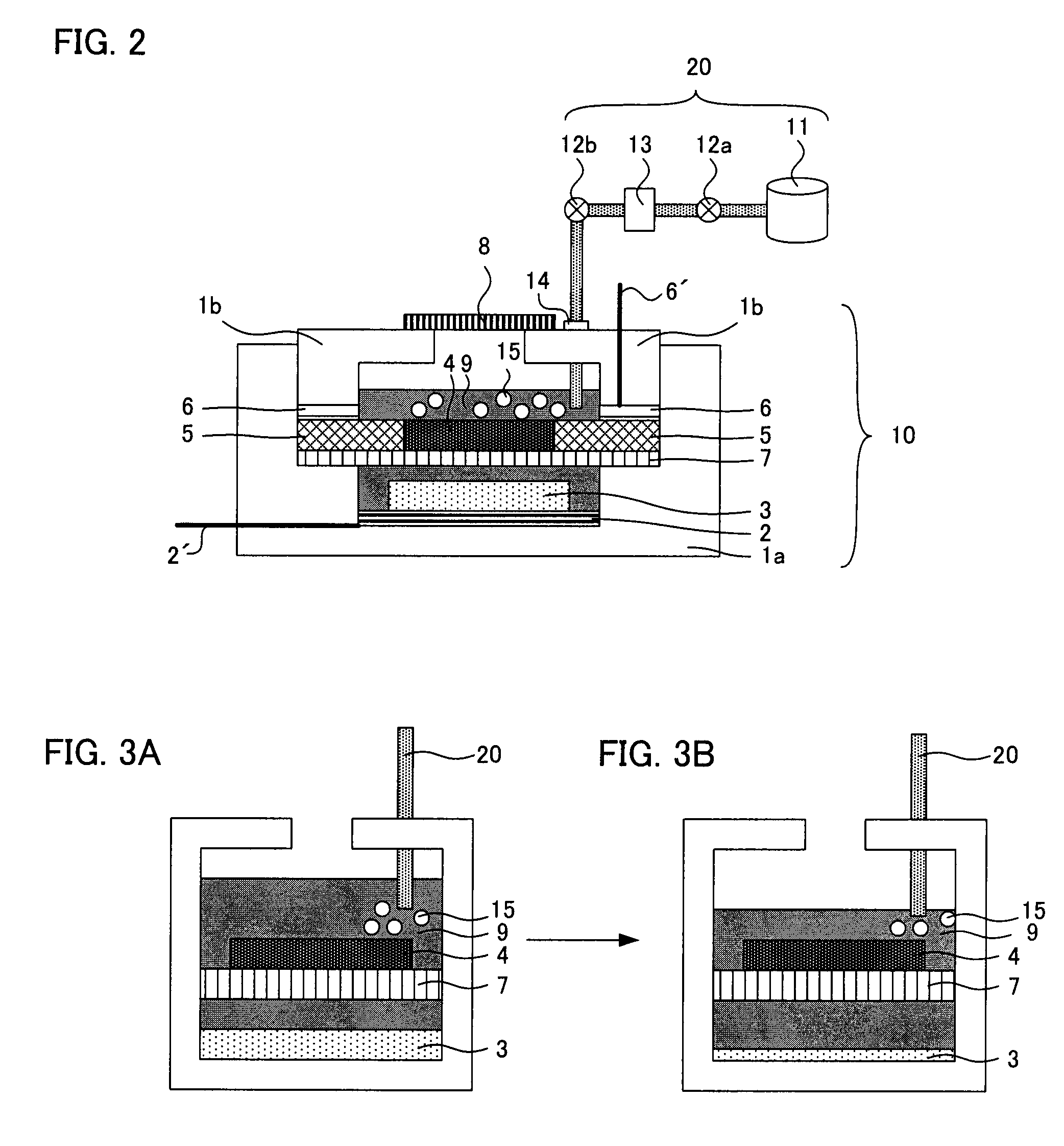
[0111]The present example will be explained with reference to FIG. 2. Assembling of the following cell was conducted in an argon box. First, a nickel mesh (thickness 150 μm, diameter 40 mm) was provided as an air cathode current collector 2 at the inside of a lower insulating case 1a made of Teflon (Registered Trademark) and having a diameter of 80 mm, and the air cathode current collector 2 was jointed to an anode lead 2′ (made of nickel). The anode lead 2′ ran through the lower insulating case 1a and penetrated to the outside. Next, an anode layer 3 was provided on the air cathode current collector 2. The anode layer 3 was a metal lithium foil and a foil having a thickness of 250 μm punched out and processed to a layer having a diameter of 20 mm was used. This anode layer 3 was pressure bonded to the mesh of the air cathode current collector 2. Then, a separator 7 (made of polyethylene, thickness 25 μm, diameter 60 mm) was provided in the upper middle of the lower insulating case ...
PUM
| Property | Measurement | Unit |
|---|---|---|
| diameter | aaaaa | aaaaa |
| thickness | aaaaa | aaaaa |
| diameter | aaaaa | aaaaa |
Abstract
Description
Claims
Application Information
 - R&D
- Intellectual Property
- Life Sciences
- Materials
- Tech Scout
- Unparalleled Data Quality
- Higher Quality Content
- 60% Fewer Hallucinations
Browse by: Latest US Patents, China's latest patents, Technical Efficacy Thesaurus, Application Domain, Technology Topic, Popular Technical Reports.
© 2025 PatSnap. All rights reserved.Legal|Privacy policy|Modern Slavery Act Transparency Statement|Sitemap|About US| Contact US: help@patsnap.com


