A solar cell module

A technology for solar cells and solar cells, applied in electrical components, circuits, photovoltaic power generation, etc., can solve problems such as low power and large internal resistance, and achieve the effects of easy commercial application, increased power, and improved photoelectric conversion efficiency.

Active Publication Date: 2016-12-07
BYD CO LTD
View PDF3 Cites 0 Cited by
  • Summary
  • Abstract
  • Description
  • Claims
  • Application Information

AI Technical Summary

Problems solved by technology

[0004] In order to solve the problems of large internal resistance and low power of the existing solar cell components, the present invention provides a solar cell that can increase the light-receiving area of ​​the light-receiving surface of the solar cell, reduce the internal resistance of the solar cell component, and increase the power of the solar cell component. battery pack

Method used


Image

  • A solar cell module
  • A solar cell module
  • A solar cell module

Examples


Embodiment 1

[0064] This example details the solar module.

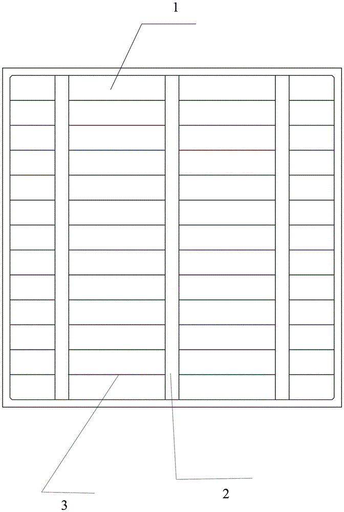
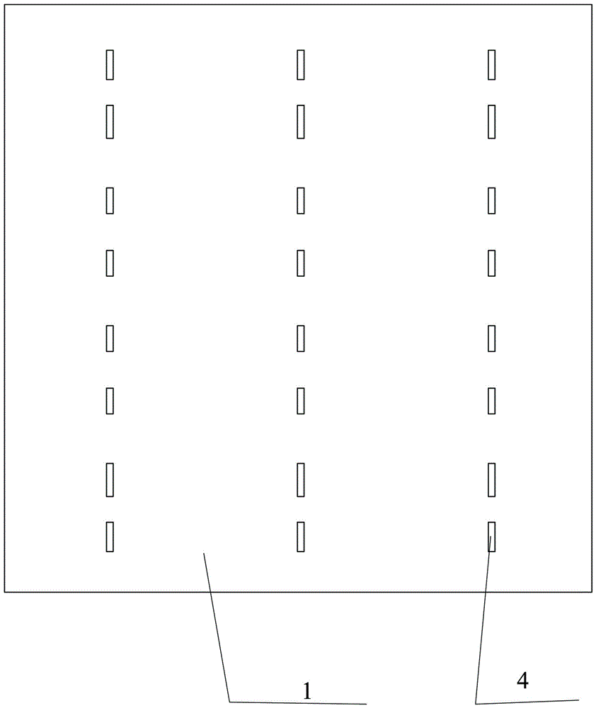
[0065] The electrode on the light-receiving surface refers to the current-leading electrode on the side that receives solar light, which is generally the negative electrode. figure 1 The light-receiving surface electrode is generally realized by printing several light-receiving surface electrode busbars 2 on the light-receiving surface of the solar cell 1, such as two or three light-receiving surface electrode busbars 2, and the light-receiving surface electrode busbar The line 2 is generally made by coating silver conductive paste and sintering. The current generated on the front of the solar cell can be collected on the main grid line 2 of the light-receiving surface electrode through a plurality of small sub-grid lines 3 connected to the light-receiving surface electrode. Lead out on gate line 2.

[0066] The backlight electrode is the current extraction electrode on the side coated with the back electric field, generally the...

Embodiment 60

[0074] Such as Figure 6 As shown, taking the series connection of two solar cells as an example, the two adjacent solar cells are defined as the first solar cell 11 and the second solar cell 12 respectively. In this way, each solar cell is welded with a ribbon, for example Figure 6 After the ribbon is welded on the first solar cell 11, the other half of the ribbon, i.e. the rectangle, is welded to the back electrode of the second solar cell 12, and then the operation is repeated to arrange the solar cells on the mold. In a row, in this way, a group of solar cell groups connected in series is completed, and then multiple groups of solar cell groups are connected in series to form a solar cell array. Or weld a triangular end of a ribbon on the light-receiving surface electrode of each solar cell, and then turn over each solar cell containing the ribbon, and weld the other end of the ribbon to the adjacent back electrode In this way, the string welding of solar cells is compl...

Embodiment 2

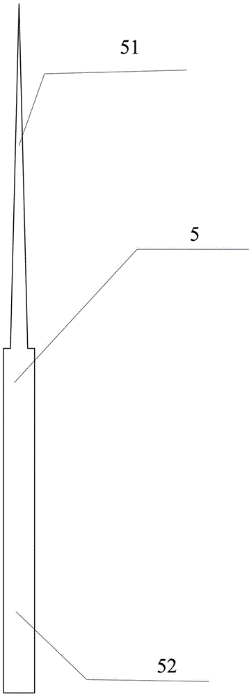
[0076] Adopt the same shape and size of the solar cell sheet as in embodiment 1, the electrode grid line printed on it is the same, adopt the conductive strip 5 of the same shape as in embodiment 1 to connect two adjacent solar cell sheets, the difference is that the isosceles triangle first The width of the widest part of the conductive strip connecting portion 51 , that is, the length of the base of the isosceles triangle is 2.5 mm, and the width of the rectangular second conductive strip connecting portion 52 is 4 mm. The size and number of solar cells 1 are the same as in Example 1, and the preparation method, the total length of the conductive strip 5 and the position and method of welding are the same as in Example 1.


PUM


Abstract

The purpose of the present invention is to provide a solar cell assembly including several solar cells and conductive strips, between the solar cells, and / or between the solar cells and the load through the conductive strips; the solar cells include light-receiving surface electrodes and The backlight surface electrode, a conductive strip is connected to the light-receiving surface electrode of a solar cell, and another conductive strip is connected to the backlight surface electrode; the conductive strip part at the connection between the conductive strip and the light-receiving surface electrode is the first conductive strip connection part, and the conductive strip The part of the conductive strip connected to the backlight electrode is the second conductive strip connection part; the width of the widest part of the first conductive strip connection part is smaller than the widest width of the second conductive strip connection part. The internal resistance is significantly reduced, reducing the power lost by itself, and the output power is significantly increased. At the same time, the photoelectric conversion efficiency of the cell can also be improved due to the increase in the light receiving rate of the light receiving surface. The solar cell assembly of the present invention is applied to a solar power station assembled with a large number of solar cell assemblies, and the output power of the entire solar power station will be greatly improved. The method of the present invention is simple, easy to implement, and low in cost, laying a solid foundation for the development of the industry Base.

Description

technical field [0001] The invention relates to the field of solar cell modules. Background technique [0002] A single crystalline silicon solar cell has a small power generation capacity and is very fragile, which is inconvenient for practical use. In practical applications, multiple solar cells must be connected and packaged into modules. For example, connect multiple battery slices into a battery pack, and then arrange multiple battery packs into a neat array. The battery slices in the same row are connected in series, and the battery slices in each row are connected in parallel. One end of the battery is welded to the back electrode of the previous battery, and the other end is welded to the front electrode of the next battery. [0003] Existing solar cell modules use ribbons whose width is generally equal to or slightly wider than the electrode grid lines to connect the light-receiving surface electrodes and the backlight surface electrodes of adjacent cells. That is...

Claims


Application Information

Patent Timeline
Patent Type & Authority Patents(China)
IPC IPC(8): H01L31/05
CPCH01L31/0508Y02E10/50
Inventor 姜占锋孙翔胡娟刘春秀冯会杰贾广帅景东亮江孝洁黄坤燕王明光
Owner BYD CO LTD
Why Eureka
Try Eureka