Variable electrical generator

a generator and variable technology, applied in the field of variable generators, can solve the problems of large dynamic range of motion, easy wear of hydraulic systems, and difficulty in implementing energy pick-up from these renewable energy systems

Active Publication Date: 2014-11-04
HAGAL TECH AS
View PDF62 Cites 3 Cited by
  • Summary
  • Abstract
  • Description
  • Claims
  • Application Information

AI Technical Summary

Benefits of technology

[0008]The present invention seeks to provide a variable electrical generator which is better adapted for coping with variable mechanical input speeds and various input rotation directions and / or linear movement directions.
[0009]The present invention seeks to provide an advanced form of variable electrical generator which is more suited to mass production whilst also providing large power generating performance and robust operation.
[0011]The invention is of advantage in that the output can be rapidly dynamically adjusted by controlling a manner in which the wavelets are combined together to synthesize the output.
[0012]Optionally, in the generator, the modules are spatially collocated with their corresponding coils to provide power signal metamorphosis at an early stage within the generator. This collocation potentially avoids a need for expensive and complex high-frequency electronic switching units later which are conventionally employed to condition outputs from conventional generators to a form suitable to feed onto an electricity distribution grid. Optionally, the variable electrical generator is beneficially implemented so that the modules are operable to generate wavelets whose duration (d) is shorter than a duration of cycle (D) of an alternating waveform of the output from the generator. Conveniently, when constructing the generator, the stator includes coils and is arranged to remain substantially stationary in operation, and the rotor includes magnets and is arranged to rotate and / or reciprocate in operation relative to the stator to induce wavelet signals in the coils. Optionally, the variable electrical generator is implemented so that the modules are electrically coupled together in a two-dimension switching matrix including at least one series path for adding potentials and at least one parallel path for current preading for generating the output. Optionally, the variable electrical generator is implemented so that the modules are operable to switch between a non-conductive state, a shorted state, a negative wavelet state and a positive wavelet state when in operation in response to control signals provided from the control arrangement. Optionally, the control arrangement is distributed between a control unit external to the modules and microcontrollers present in the modules. Optionally, when implementing the variable electrical generator, the modules are coupled in communication with the control arrangement via an optical data highway. More optionally, when implementing the variable electrical generator, the optical data highway is operable to direct data selectively between the control arrangement and the modules by way of wavelength division multiplexing (WDM). More optionally, the variable electrical generator is implemented so that the modules are operable to communicate diagnostic signals regarding their operating status to the control arrangement, and to receive control signals from the control arrangement concerning timing information and / or polarity information in respect of their respective wavelets.
[0026](b) adjusting wavelet selection in the generator to absorb or inject electrical power into the grid so as to assist to stabilize the grid against deviations in voltage and / or frequency of said grid resulting from said degree of electrical loading.

Problems solved by technology

Moreover, extreme weather conditions often result in a large dynamic range of motion at various times throughout a year.
In consequence, energy pickoff from these renewable energy systems is often technically difficult to implement.
However, hydraulic systems are prone to wear, and are relatively energy inefficient on account of viscous drag occurring in hydraulic fluids employed therein.
Several types of variable speed generators are known, but they are often very rough devices which are not really ideal for applications such as wind power or tidal energy production.
These approaches (i) and (ii) are relatively expensive to implement, especially in respect of electronic apparatus required to rectify and phase form the generated electrical power provided by the generator.

Method used


Image

  • Variable electrical generator
  • Variable electrical generator
  • Variable electrical generator

Examples


Embodiment Construction

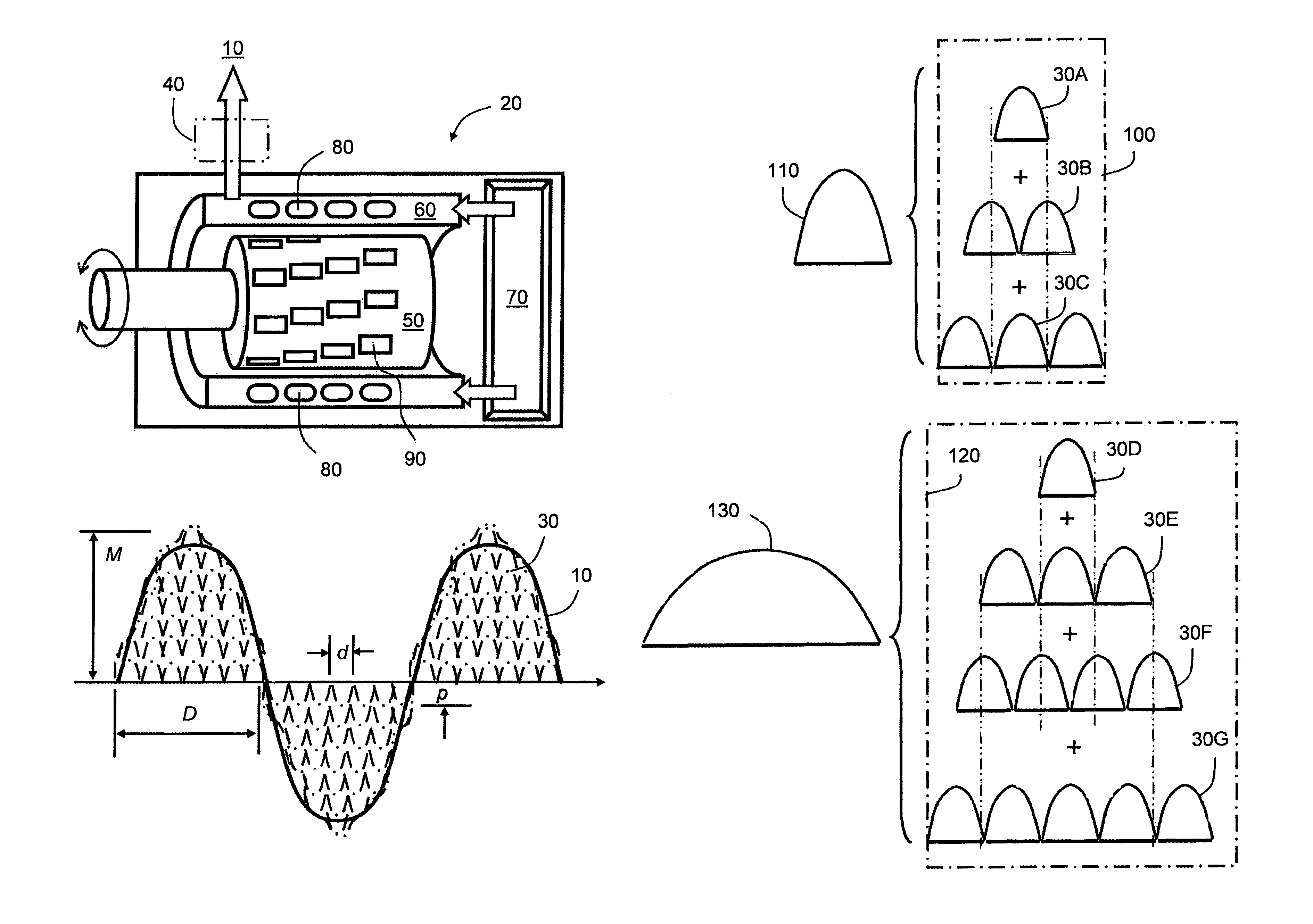
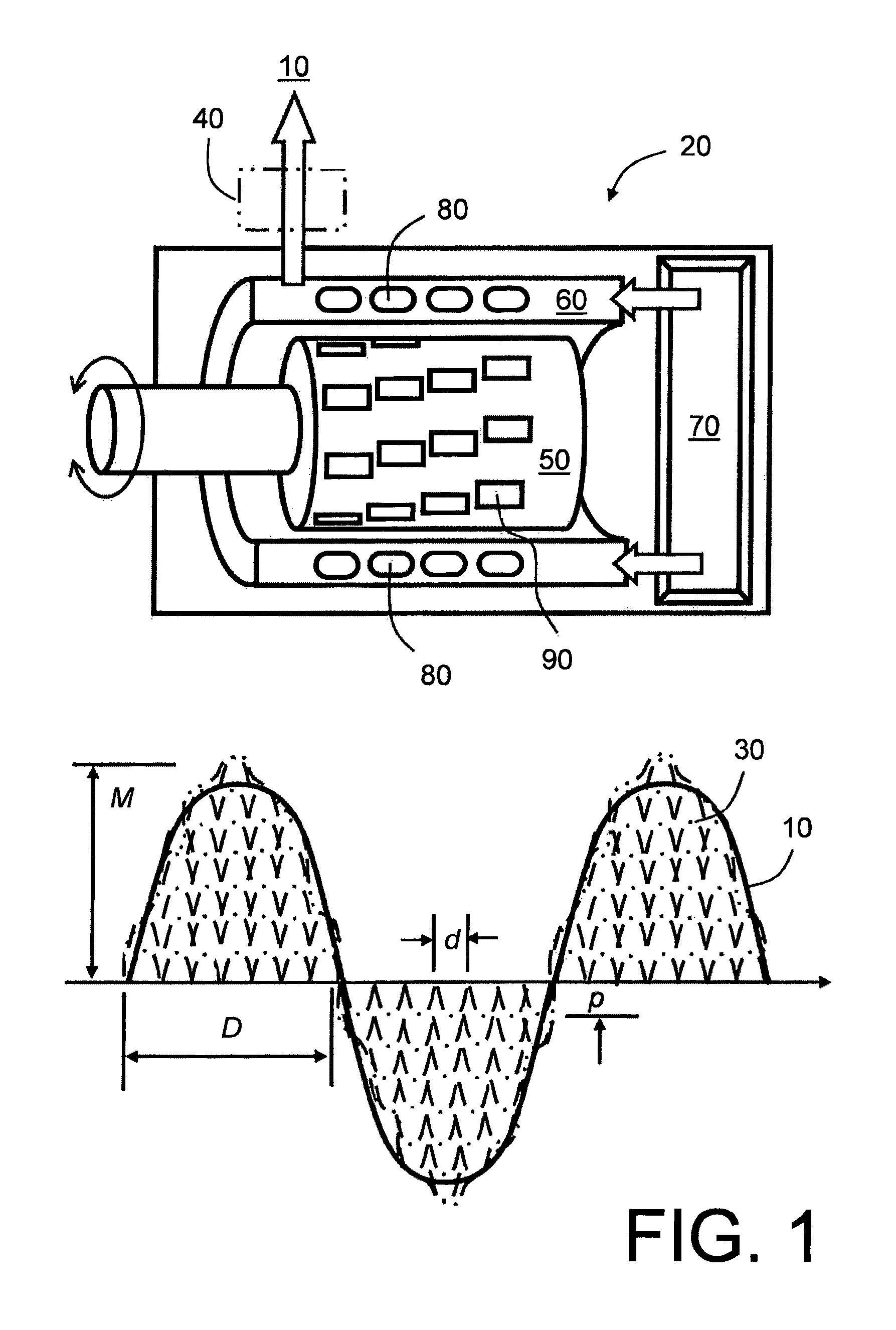
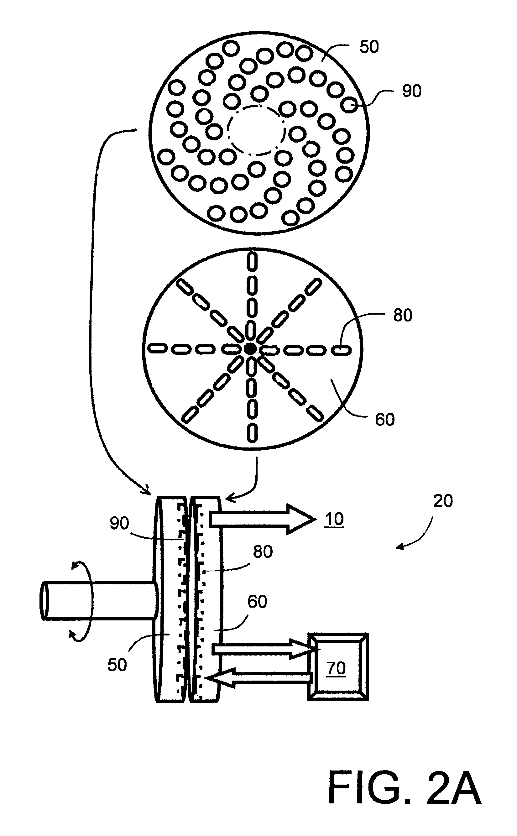
[0044]The present invention is based upon a concept which is illustrated in FIG. 1, namely that an alternating power output 10 provided from an electrical generator 20 is susceptible to being synthesized by selectively switching a large number of smaller wavelets 30 which have a magnitude p and a duration d which are considerably smaller and shorter respectively than a magnitude M and a duration D of the alternating power output 10 provided from the generator 20. If required, a filter 40, for example implemented by a combination of inductors and capacitors, may be employed to filter high-order harmonic signal components present in the output 10 from the generator 20. A benefit of this approach is that the wavelets 30 are capable of being switched rapidly in response to dynamically changing input rotation directions or rotation speeds of a rotor 50 of the generator 20. Moreover, mass-produced solid state electronic modules 80 can be employed which are dedicated to switching their res...


PUM

PropertyMeasurementUnit
poweraaaaaaaaaa
output poweraaaaaaaaaa
blocking voltage performanceaaaaaaaaaa

Abstract

A variable electrical generator (20) is operable to convert mechanical motion to electrical power. The generator (20) includes at least a stator element (60) and a rotor element (50) including coils (320) and magnets (90). The generator (20) includes a configuration of modules (80) including the coils (320) for generating wavelets (30) in response to the coils (320) interacting magnetically with the magnets (90), and a control arrangement (70) for combining the wavelets (30) for generating a composite synthesized power output (10) from the generator (20). A method of maintaining a variable generator (20) includes steps of: (a) determining operating status of modules (80) of the generator (20); (b) unplugging and replacing one or more defective modules (80) as identified in step (a). The generator (20) is susceptible to being used in renewable energy system, for example in a tidal water turbine, in a wind turbine, in association with an oscillating wind vane, in association with an ocean float, in a hydroelectric turbine, in a steam turbine.

Description

[0001]This application is a 35 U.S.C. 371 National Phase Entry Application from PCT / NO2011 / 000099, filed Mar. 23, 2011, which claims the benefit of Norwegian Patent Application No. 20100443 filed on Mar. 23, 2010 in the Norwegian Intellectual Property Office, the disclosures of which are incorporated herein in their entirety by reference.FIELD OF THE INVENTION[0002]The present invention relates to variable electrical generators for converting mechanical rotational and / or displacement energy to electrical energy, for example to a generator which is operable to vary dynamically its electrical output as well as coping with dynamically changing mechanical input rotation and / or reciprocating speeds. Moreover, the present invention also relates to methods of operating these variable electrical generators. Furthermore, the present invention concerns methods of constructing these variable electrical generators. Additionally, the present invention relates to software products executable on c...

Claims


Application Information

Patent Timeline
Patent Type & Authority Patents(United States)
IPC IPC(8): H02K17/44H02K21/14H02K21/12F03G7/08H02P25/22H02K7/18H02K21/24H02K7/20H02K11/00H02P9/00H02K1/18F02B63/04H02K21/22F03B13/12H02P9/48F03D9/00H02P27/16
CPCF03D9/002H02K2213/12H02K21/24H02K21/12Y02E10/725H02P2009/004H02P9/48F03B13/12Y02E10/38H02P25/22H02P2009/003H02P27/16F05B2220/7064H02K1/18H02K21/22H02K11/0073H02K21/14H02P2101/10H02P2101/15Y10T29/4973H02K11/33F03D9/25F03D9/255Y02E10/30Y02E10/72
Inventor THORESEN, KENT
Owner HAGAL TECH AS
Why Eureka
Try Eureka