
Cooperative beam forming method, apparatus and base station

a beam forming and beam technology, applied in the field of multi-media broadcast multicast, can solve the problems of limited performance improvement, and achieve the effect of improving the receiving improving the performance of single cell mbms

Active Publication Date: 2014-11-04
ALCATEL LUCENT SAS
View PDF13 Cites 6 Cited by
  • Summary
  • Abstract
  • Description
  • Claims
  • Application Information

AI Technical Summary

Benefits of technology

The patent proposes a new method to improve the performance of multimedia broadcasts in mobile networks. This method involves using a fixed grid of beams to create a more stable and effective signal for each individual cell. This can improve the receiving performance of single cell multimedia broadcasts and lead to better overall performance of the network.

Problems solved by technology

As a result from above analysis, the performance improvement is still limited and more advanced technology is necessary to be investigated.

Method used


Image

  • Cooperative beam forming method, apparatus and base station
  • Cooperative beam forming method, apparatus and base station
  • Cooperative beam forming method, apparatus and base station

Examples


Embodiment Construction

[0055]Hereinafter, the present invention is described with reference to the drawings. In the following description, some detailed embodiments are only used for the aim of description, which should not be understood as any limitation to the present invention, but only as examples. When it might cause ambiguous understanding of the present invention, the traditional structure or composition will be omitted.

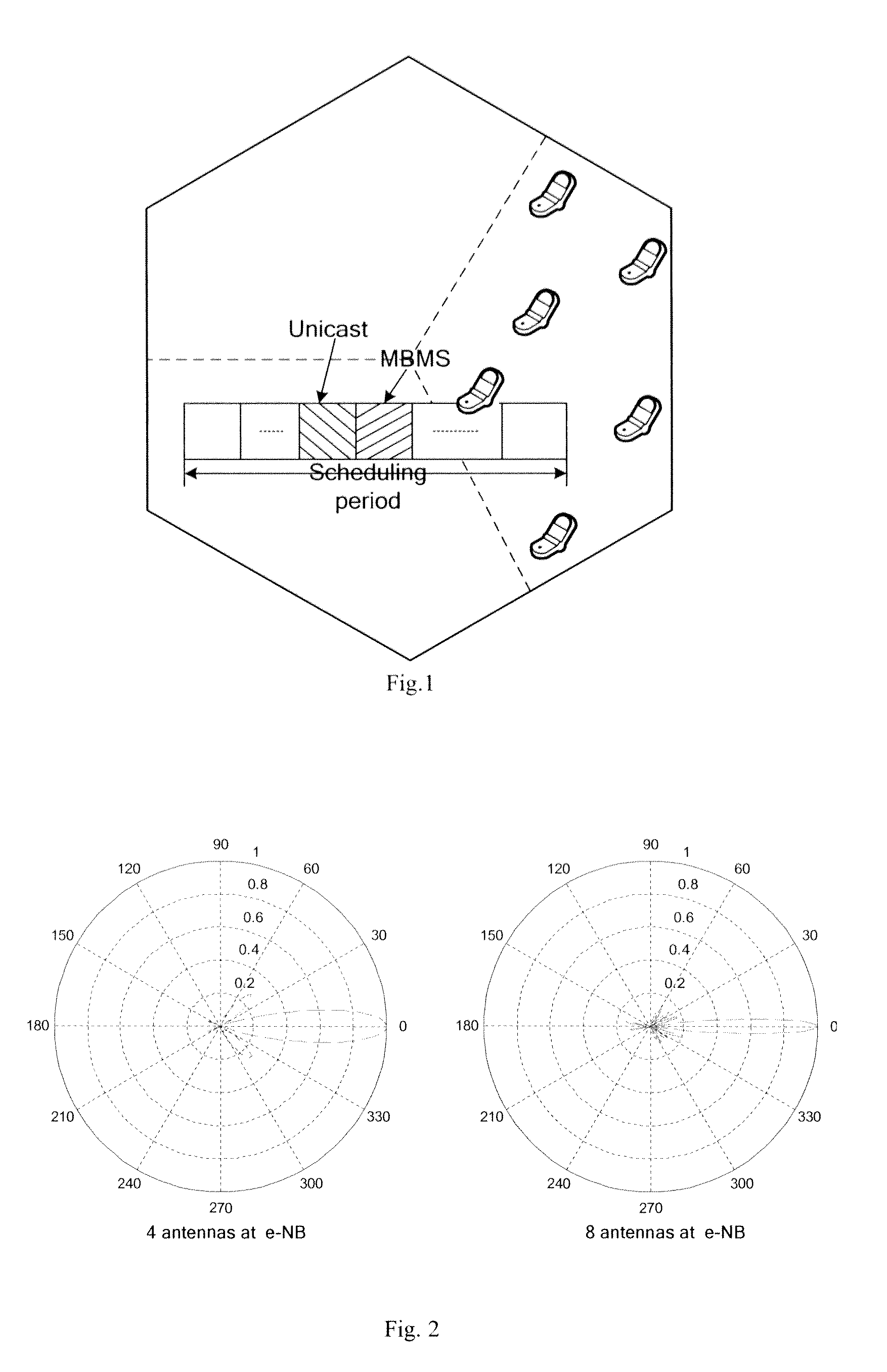
[0056]Before concepts according to the present invention are introduced, firstly all of users (unicast+MBMS) are classified into the following four kinds: ① unicast UE near the eNB, for the purpose of convenience, this kind of user is denoted as “u-c”; ② SC MBMS UE near the eNB, for the purpose of convenience, this kind of user is denoted as “m-c”; ③ unicast UE at cell edge, for the purpose of convenience, this kind of user is denoted as “u-e”; ④ SC MBMS UE at cell edge, for the purpose of convenience, this kind of user is denoted as “m-e”.

[0057]It should be noted that u-c user and ...


PUM


Abstract

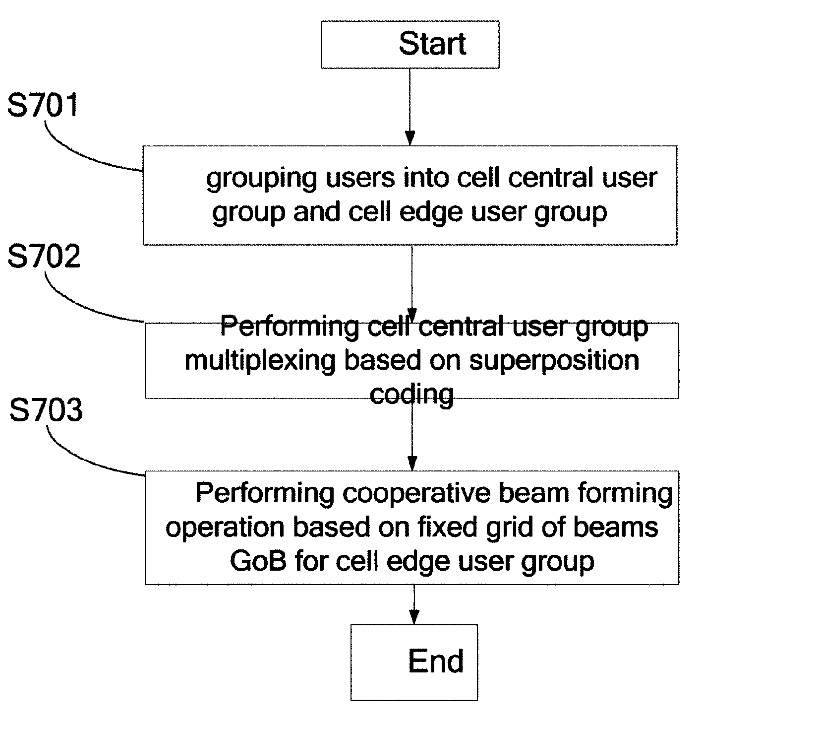
The present invention proposes a method, device and base station for cooperative beam forming based on MBMS fixed grid of beams GoB. The cooperative beam forming method comprises following steps: grouping users into cell central user group and cell edge user group (S701); performing cell central user group multiplexing based on superposition coding (S702); performing cooperative beam forming operation based on fixed grid of beams GoB for cell edge user group (S703).

Description

FIELD OF THE INVENTION[0001]The present invention relates to multimedia broadcast multicast field, more particularly, to a cooperative beam forming method, apparatus and base station based on fixed grid of beams GoB of MBMS (Multimedia Broadcast Multicast Service).BACKGROUND OF THE INVENTION[0002]The concept of BF (Beam Forming) derives from smart antenna (SA). The basic principle of SA is that forming a directional beam via process at transmitter using the correlation of channel impulse response of half wavelength-distance antennas array to increase the signal-to-noise ratio (SNR) at receiver and extend coverage area of system. Traditional BF is usually acting on single signal stream, that is, the transmit signal is multiplied with a weight factor and then is transmitted via a plurality of antennas. Normally such gain is called as array gain. Then, the detailed meanings of BF extends with the continuous deeper research of multiple-input and multiple-output (MIMO) system, in which d...

Claims


Application Information

Patent Timeline
Patent Type & Authority Patents(United States)
IPC IPC(8): H04W4/00H04B7/02H04B7/06
CPCH04B7/024H04B7/0639H04B7/0617
Inventor ZHANG, BIJUNWANG, HEHU, ZHONGJI
Owner ALCATEL LUCENT SAS
Learn More