Fuel cell membrane-electrode assembly and production method therefor

a technology of fuel cell membrane and production method, which is applied in the direction of cell components, metal/metal-oxide/metal-hydroxide catalysts, physical/chemical process catalysts, etc., can solve the problems of difficult effective increase of exposed surface area, difficult dispersion of small metal catalyst particles, and high cost of electrode catalysts, etc., to restrain the decline of fuel cell durability and improve catalyst utilization ra

Active Publication Date: 2014-12-09
TOYOTA JIDOSHA KK
View PDF41 Cites 0 Cited by
  • Summary
  • Abstract
  • Description
  • Claims
  • Application Information

AI Technical Summary

Benefits of technology

[0025]It is a first object of the invention to improve the catalyst utilization rate in a fuel cell membrane-electrode assembly. Furthermore, it is a second object of the invention to restrain the decline of the durability of a fuel cell caused by the oxidation corrosion of a support that supports a catalyst.

Problems solved by technology

Metal catalysts, such as platinum or the like, that are used as electrode catalysts are very expensive.
However, small metal catalyst particles are difficult to disperse, and very easily aggregate.
Therefore, the particle size reduction finds it difficult to effectively increase the exposed surface area.
This is because in a thick catalyst layer, the diffusion of the reactant gas, protons and electrons is likely to be impeded.
However, such a support-less metal catalyst particle very easily aggregates, depending on the particle diameter thereof.
Thus, it is very difficult to form a catalyst layer in which a metal catalyst particle is highly dispersed.
Such a large-particle diameter platinum black may be able to be dispersed to a high degree, but is not able to sufficiently improve the catalyst utilization rate due to its small surface area.
Furthermore, the ratio between the platinum black and the fluorine-containing ion exchange resin recommended in JP-A-2002-151088 (platinum black:fluorine-containing ion exchange resin=0.2:0.8 to 0.9:0.1 (mass ratio)) may suffer from large catalyst layer resistance and therefore decline of the cell output because the amount of fluorine-containing ion exchange resin is rather large.
Furthermore, in this technology, it is sometimes difficult to fabricate electrodes where the electrode reactions efficiently progress.
Generally, the carbon material having large surface area (generally, 300 m2 / g or greater) which is used as a catalyst support as mentioned above is low in oxidation corrosion resistance.
In a unit cell where abnormality has occurred in the state of supply of the fuel and therefore fuel deficiency has occurred, the protons and the electrons produced by the oxidation of the fuel become insufficient.
This oxidation corrosion of the carbon material decomposes and depletes the carbon material.
The decomposition, depletion or the like of the carbon material that is an electrically conductive material lowers the electrical conductivity, and causes increased resistance due to bad contact.
Thus, due to the oxidation corrosion of the carbon material, the power generation performance of the fuel cell considerably declines, and stable power generation performance cannot be delivered.
Furthermore, even if the fuel deficiency state is resolved, there may occur a case where during the transition from the fuel deficiency state to a normal power generating state, a partial cell reaction caused by non-uniform distribution of the fuel on the fuel electrode side results in a local high electrical potential on the oxidant electrode.
In consequence, the oxidation corrosion of the carbon material occurs on the oxidant electrode side as well, and concomitantly various problems as mentioned above occur on the oxidant electrode side as well.
Because the oxidation of the carbon material in the fuel electrode and the oxidant electrode as mentioned above is a irreversible reaction, the resolution of the fuel deficiency will not bring the performance of the fuel cell back to the state preceding the fuel deficiency.
However, because the screen printing paste is required to have high boiling point and high viscosity, small-particle diameter platinum black is likely to thermally aggregate in the paste.
Therefore, in the case where small platinum black particles in the nano-size are incorporated in a non-supported state, the utilization rate thereof as a catalyst is likely to decline.

Method used


Image

  • Fuel cell membrane-electrode assembly and production method therefor
  • Fuel cell membrane-electrode assembly and production method therefor
  • Fuel cell membrane-electrode assembly and production method therefor

Examples


Embodiment Construction

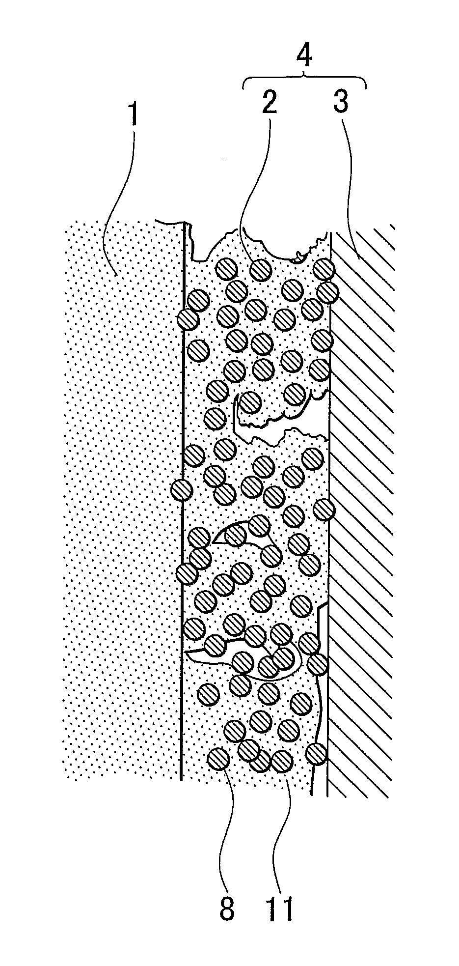
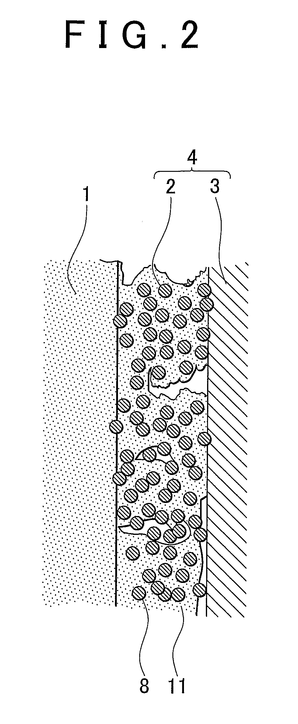
[0058]A fuel cell membrane-electrode assembly (hereinafter, referred to simply as “membrane-electrode assembly”) of an embodiment of the invention is a fuel cell membrane-electrode assembly that has a fuel electrode at one surface side of an electrolyte membrane, and an oxidant electrode at the other surface side thereof. At least one of the fuel electrode and the oxidant electrode has a non-supported-catalyst containing catalyst layer that contains a metal catalyst nanoparticle of 0.3 nm to 100 nm in primary particle diameter that is not supported on a support, and an electrochemically active surface area of the metal catalyst nanoparticle is 10 m2 / g to 150 m2 / g, and a layer thickness of the non-supported-catalyst containing catalyst layer is less than or equal to 10 μm.

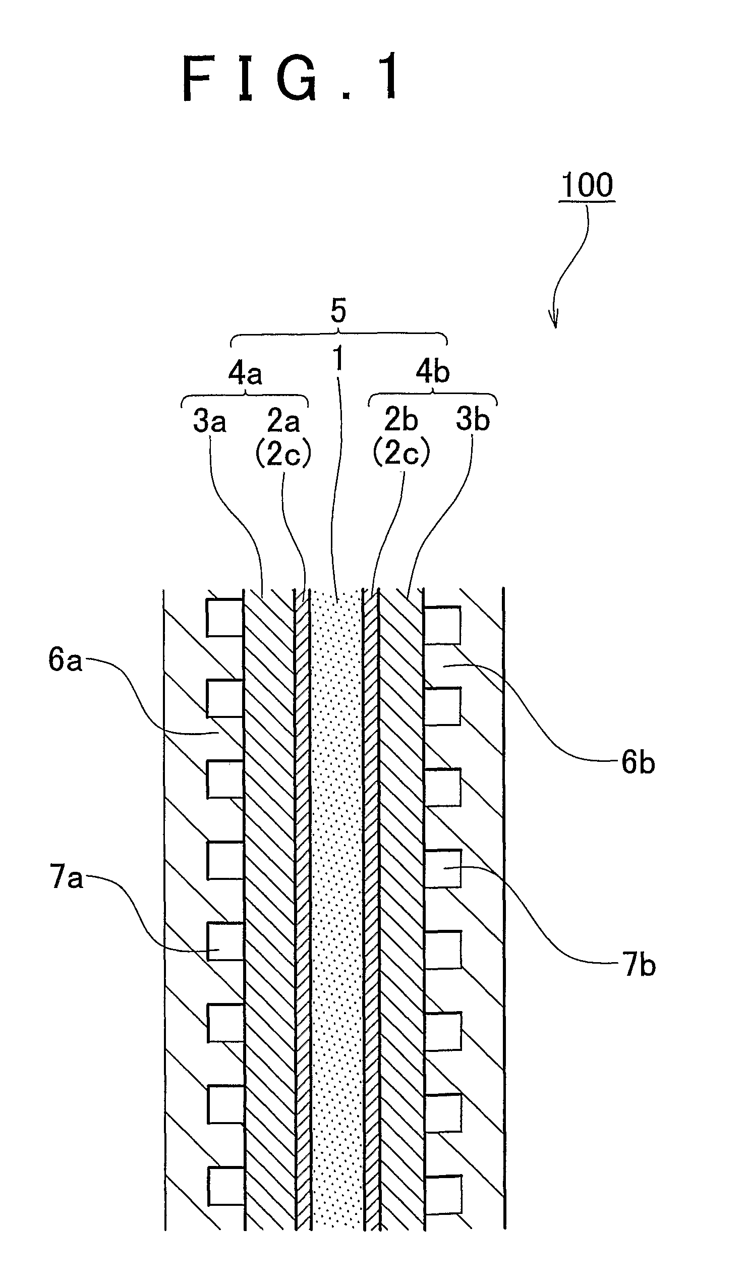
[0059]An fuel cell membrane-electrode assembly of an embodiment of the invention will be described hereinafter with reference to FIGS. 1 and 2. FIG. 1 is a diagram showing an embodiment of the fuel cell membrane-ele...


PUM

PropertyMeasurementUnit
primary particle diameteraaaaaaaaaa
thicknessaaaaaaaaaa
particle diameteraaaaaaaaaa

Abstract

A fuel cell membrane-electrode assembly having a fuel electrode and an oxidant electrode has a non-supported-catalyst containing catalyst layer that contains a metal catalyst nanoparticle of 0.3 nm to 100 nm in primary particle diameter that is not supported on a support, and an electrochemically active surface area of the metal catalyst nanoparticle is 10 m2 / g to 150 m2 / g, and a layer thickness of the non-supported-catalyst containing catalyst layer is less than or equal to 10 μm.

Description

[0001]This is a 371 national phase application of PCT / IB2007 / 000733 filed 22 Mar. 2007, claiming priority to Japanese Patent Application No. 2006-111838 filed 14 Apr. 2006, the contents of which are incorporated herein by reference.BACKGROUND OF THE INVENTION[0002]1. Field of the Invention[0003]The invention relates to a fuel cell membrane-electrode assembly and a production method therefor.[0004]2. Description of the Related Art[0005]Fuel cells directly convert chemical energy into electric energy by supplying a fuel and an oxidant to two electrically connected electrodes and electrochemically causing oxidation of the fuel. Unlike thermal power plants, the fuel cells are free from the restrictions of the Carnot cycle, and exhibit high energy-conversion efficiency. Ordinarily, the fuel cells are constructed by stacking a plurality of unit cells that have, as a basic structure, a membrane-electrode assembly formed by sandwiching an electrolyte membrane between a pair of electrodes. I...

Claims


Application Information

Patent Timeline
Patent Type & Authority Patents(United States)
IPC IPC(8): H01M4/88H01M8/10H01M4/86H01M4/92
CPCH01M4/886H01M4/928Y02E60/50H01M4/8668H01M4/8828H01M4/92H01M4/8673H01M4/881Y10T29/49115H01M8/1004H01M8/1018H01M2008/1095
Inventor NAOHARA, HIDEOORIKASA, YUICHIKATO, MANABU
Owner TOYOTA JIDOSHA KK
Why Eureka
Try Eureka