CPP-type magnetoresistance effect element and magnetic disk device using side shield layers

a magnetoresistance effect and magnetic disk technology, applied in the field of cpp-type magnetoresistance effect elements and magnetic disk devices using side shield layers, can solve the problems of limited operating current from a reliability perspective, limited area of elements, and reduced sensitivity, so as to improve linear recording density and improve sensitivity.

Active Publication Date: 2014-12-16
TDK CORPARATION
View PDF9 Cites 4 Cited by
  • Summary
  • Abstract
  • Description
  • Claims
  • Application Information

AI Technical Summary

Benefits of technology

[0017]The objective of the present invention is to provide a magnetoresistive effect element (MR element) that can improve the linear recording density by adopting a structure, which can narrow a read gap (space between the upper and lower shield layers), in order to respond to the recent demand for ultrahigh recording density, and, that can suppress false writing of a signal into a medium, demagnetization or degauss of a recorded signal in a medium, and that can improve a sensitivity (reproducing characteristic) to an external magnetic field to be detected; a thin film magnetic head including the MR element; a head gimbal assembly (HGA) including the thin film magnetic head; and a magnetic disk apparatus.
[0020]Further, in the invention (first invention), because the side shield layers are established at both sides of the MR part fulfilling a function as a sensor in the track width direction, the resolution capacity in the track width direction can be improved, and the sensitivity (reproducing characteristic) relative to the external magnetic field to be detected in response to the ultrahigh recording density can be improved.
[0021]In addition, although the second ferromagnetic layer is indirectly magnetic-coupled with the lower shield layer, the first ferromagnetic layer will not be magnetic-coupled with the upper shield layer. Although it is also possible to incline the magnetization of the first ferromagnetic layer relative to the track width direction by indirectly magnetically coupling the first ferromagnetic layer with the upper shield layer, because the magnetic coupling between the upper shield layer and the first ferromagnetic layer becomes weak, an angle of inclination of the magnetization of the first ferromagnetic layer relative to the track width direction may become smaller because of effects of a magnetostatic coupling between the first ferromagnetic layer and the second ferromagnetic layer and a demagnetizing field. These may cause a decrease in the reproducing output and an increase in asymmetry of reproducing waveform, and may reduce the sensitivity to the external magnetic field to be detected.
[0022]However, according to the invention (first invention) described above, since at least the magnetization of the first ferromagnetic layer is inclined due to the application of the bias magnetic field from the side shield layers, the angle of inclination of the magnetization of the first ferromagnetic layer relative to the track width direction can be maintained at a predetermined angle; therefore, the sensitivity to the external magnetic field to be detected can be improved.
[0034]According to the present invention, in order to respond to the recent demand for the ultrahigh recording density, an MR element that can improve the linear recording density by adopting the structure that can narrow a read gap (space between the upper and lower shield layers), and that can prevent false writing of a signal into a medium and demagnetization or degauss of a recorded signal in a medium, and, that can improve a sensitivity (reproducing characteristic) to an external magnetic field to be detected; a thin film magnetic head including the MR element; an HGA including the thin film magnetic head; and a magnetic disk apparatus can be provided.

Problems solved by technology

Because of the narrower track of the reproducing element and shortening of the element height in association with this, an area of the element is reduced, but because a heat dissipation efficiency is decreased with the conventional structure in association with the reduction of the area, there is a problem that an operating current is restricted from a viewpoint of reliability.
However, in the TMR element, an insulating film, such as an aluminum oxide (AlOx) film or a magnesium oxide (MgO) film, has to be intervened between the two ferromagnetic layers in order to obtain a tunnel effect, and inconvenience that it becomes difficult to generate a strong exchange coupling between the two ferromagnetic layers can occur.
As a result, it becomes extremely difficult to bring the magnetizations of the two ferromagnetic layers to an antiparallel state.
Further, in association with the recent ultrahigh recording density, it becomes essential to improve the resolution in a cross-track direction in the CPP-GMR element, but in the CPP-GMR element using the DFL element structure in the prior art, there is a problem where the resolution capacity in the cross-track direction is still insufficient.
If the thickness of the permanent magnet HM is attempted to be increased and the read cap is attempted to be narrowed, the space between the permanent magnet HM and the upper and lower shield layers 403 and 404 becomes smaller, respectively, and a bias magnetic field to be generated from the permanent magnet HM passes through the upper and lower shield layers 403 and 404, and the application of the bias magnetic field to the element becomes insufficient and a problem that a resistive change of the element can no longer be detected can occur.
However, the bias magnetic field from the permanent magnet HM may leak from the element, and due to the leaked magnetic field, a problem(s) that a signal is falsely written into a medium or a signal recorded in a medium demagnetizes or degausses may also occur.

Method used


Image

  • CPP-type magnetoresistance effect element and magnetic disk device using side shield layers
  • CPP-type magnetoresistance effect element and magnetic disk device using side shield layers
  • CPP-type magnetoresistance effect element and magnetic disk device using side shield layers

Examples


experimental example 1

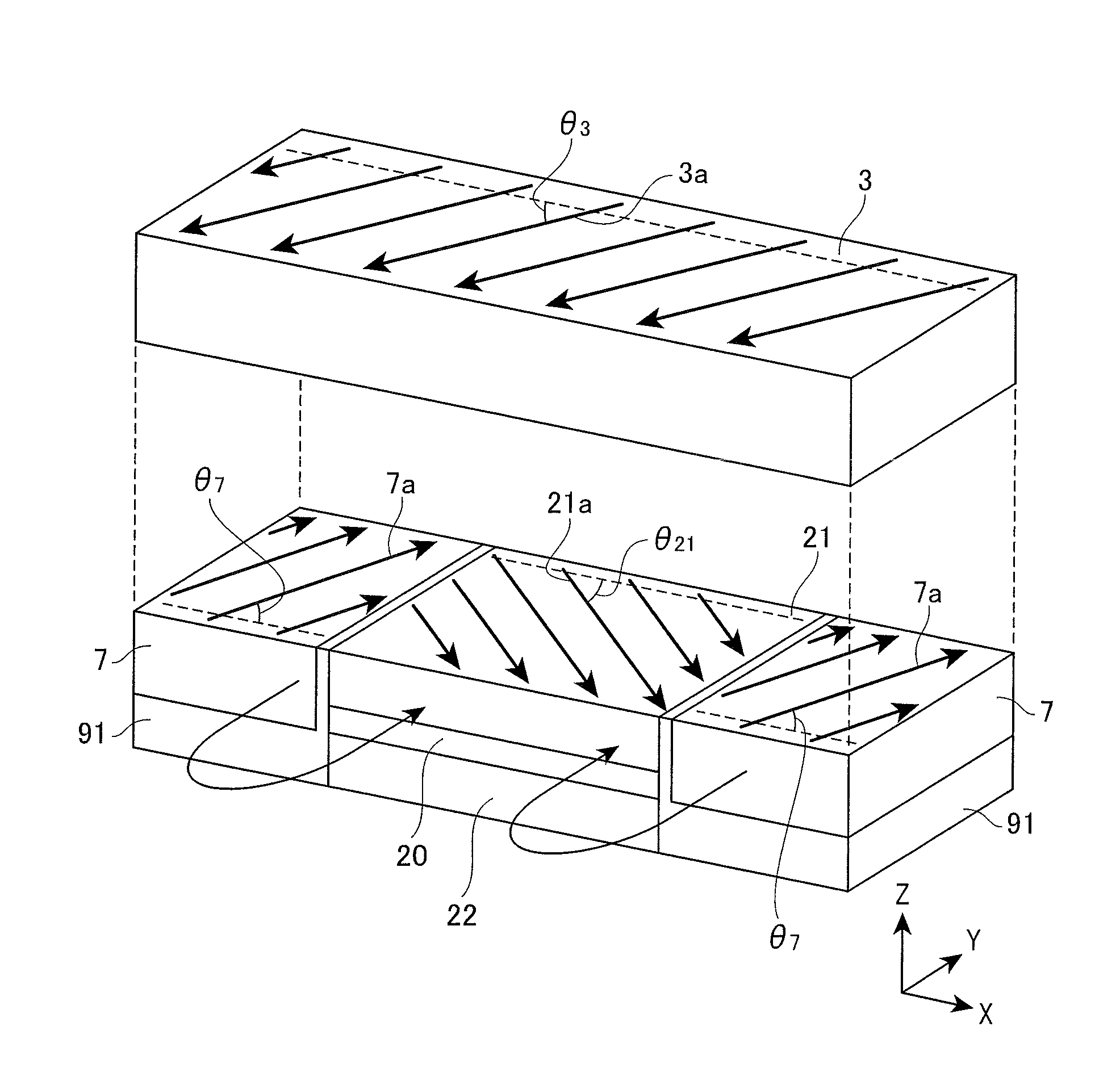
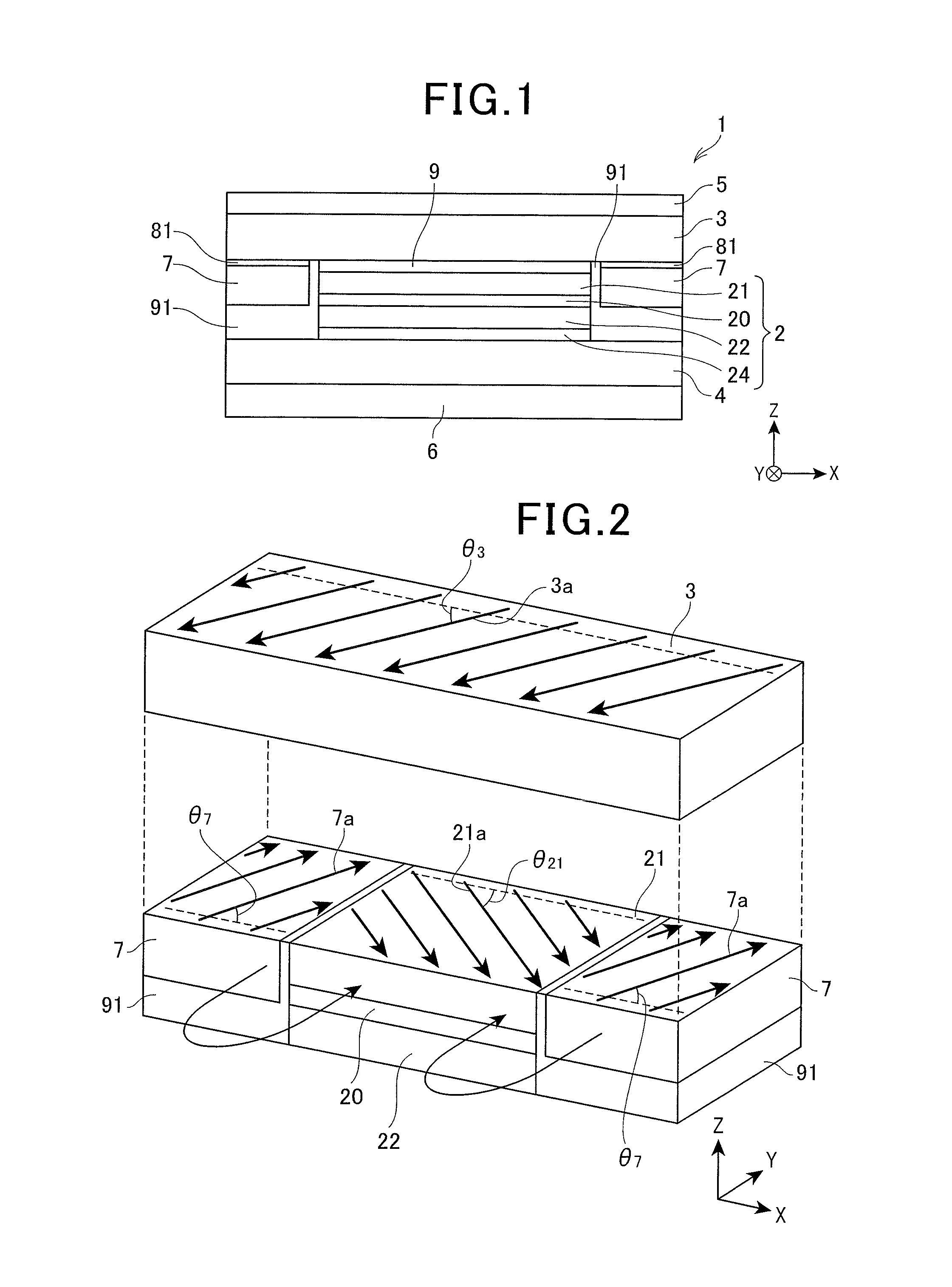
[0181]For the angle θ21 of the magnetization 21a of the first ferromagnetic layer 21 when the angle θ2 of the magnetization 7a of the side shield layer 7 in the MR element 1 having the configuration shown in FIG. 4 was fluctuated within a predetermined range, a simulation analysis experiment (calculation of an angle of magnetization by LLG simulation) was conducted.

[0182]In the MR element 1 used in this simulation analysis experiment, the first upper shield layer 31, the second upper shield layer 32 and the side shield layer 7 were all regarded as magnetization pinned layers where the angles θ3 and θ7 of their magnetizations 31a, 32a and 7a were pinned at a predetermined angle(s), respectively. Further, the first lower shield layer 41 and the second lower shield layer 42 were regarded as magnetization pinned layers where the angle θ4 of their magnetizations 41a and 42a were pinned to 45 degrees, respectively, and the magnetizations 41a and 42a were in an antiparallel state to each o...

experimental example 2

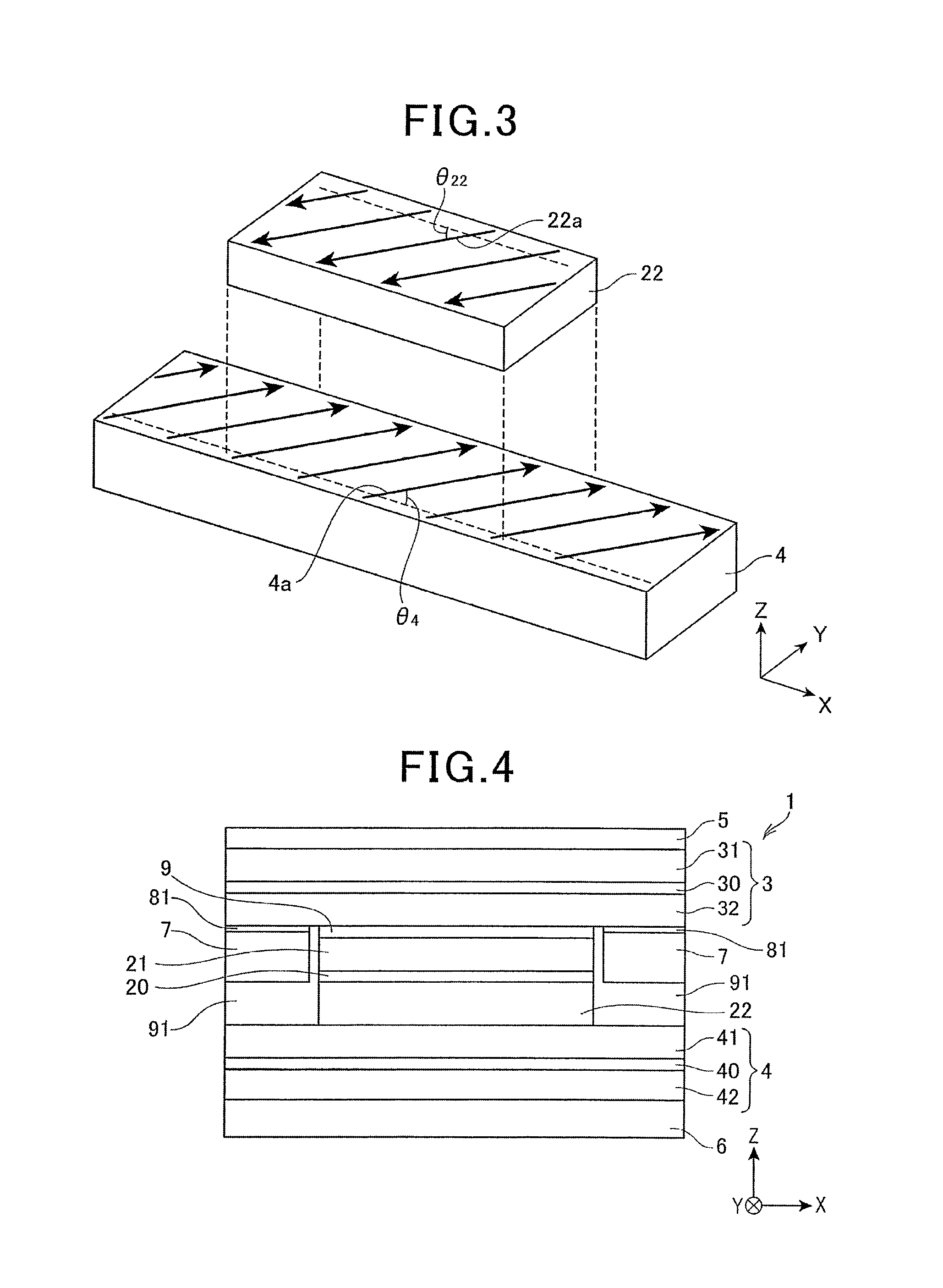
[0185]In the MR element 1 of Experimental example 1, without pinning the angle θ22 of the magnetization 22a of the second ferromagnetic layer 22, the simulation analysis experiment (calculation of an angle of magnetization by the LLG simulation) was conducted as similar to Example 1.

[0186]In the MR element 1 used in this simulation analysis experiment, the first upper shield layer 31, the second upper shield layer 32 and the side shield layer 7 were regarded as magnetization pinned layers where the angles θ3 and θ7 of the magnetizations 3a and 7a were pinned to 68.3 degrees. Further, the first lower shield layer 41 and the second lower shield layer 42 were regarded as magnetization pinned layers where the angle θ4 of their magnetizations 41a and 42a was pinned to a predetermined angle.

Furthermore, the intensity of exchange-coupling J (erg / cm2) between the second lower shield layer 42 and the second ferromagnetic layer 22 in the MR element 1 was set at −0.2 erg / cm2.

[0187]A graph show...

experimental example 3

[0188]In the MR element 1 shown in FIG. 4 and FIG. 6A, for the angles θ21 and θ22 of the magnetizations 21a and 22a of the first ferromagnetic layer 21 and the second ferromagnetic layer 22 when the thickness T71b of the second side shield layer 71b became fluctuated without pinning the angles θ21 and θ22 of the magnetizations 21a and 22a of the first ferromagnetic layer 21 and the second ferromagnetic layer 22, a simulation analysis experiment (calculation of an angle of magnetization by LLG simulation) was conducted.

[0189]In the MR element 1 used in this simulation analysis experiment, the first upper shield layer 31, the second upper shield layer 32 and the side shield layer 7 were regarded as magnetization pinned layers where the angles θ3 and θ7 of the magnetizations 31a, 32a and 7a were pinned to 68.3 degrees. Further, the first lower shield layer 41 and the second lower shield layer 42 were regarded as magnetization pinned layers where the angle θ4 of the magnetizations 41a a...


PUM

PropertyMeasurementUnit
thicknessaaaaaaaaaa
total thicknessaaaaaaaaaa
thicknessaaaaaaaaaa

Abstract

An MR element includes an MR part and upper and lower shield layers in a CPP structure. The MR element has side shield layers so as to interpose the MR part between the side shield layers in a track width direction. The MR part comprises a nonmagnetic intermediate layer and first and second ferromagnetic layers so as to interpose the nonmagnetic intermediate layer between the ferromagnetic layers. Each of the upper and lower shield layers has an inclined magnetization structure such that its magnetization is inclined relative to the track width direction. The side shield layers are magnetically coupled with the upper shield layer, respectively. The second ferromagnetic layer is indirectly magnetically coupled with the lower shield layer via an exchange-coupling functional gap layer. The side shield layer applies a bias magnetic field to the first ferromagnetic layer; and magnetizations of the first and second ferromagnetic layers are substantially orthogonal.

Description

BACKGROUND OF THE INVENTION[0001]1. Field of the Invention[0002]The present invention relates to a magnetoresistive effect element (MR element) for reading magnetic field intensity of a magnetic recording medium as a signal, a thin film magnetic head including the MR element, a head gimbal assembly (HGA) and a magnetic disk apparatus.[0003]2. Description of the Related Art[0004]Recently, in association with high recording density of a hard disk (HDD), improvement of performance of the thin film magnetic head is in demand. As the thin film magnetic head, a composite-type thin film magnetic head with a structure where a reproducing head having the MR element exclusive for reading and a recording head having an induction-type magnetic transduction element exclusive for writing are laminated is widely used.[0005]At present, as the reproducing head, an MR element with a so-called current-in-plane structure (CIP-GMR element) that is activated by applying an electric current on a film surf...

Claims


Application Information

Patent Timeline
Patent Type & Authority Patents(United States)
IPC IPC(8): H01L43/08G11B5/39
CPCG01R33/0076G11B5/3932G11B5/3912G01R33/00G01R33/093H01L43/08G01R33/098
Inventor YAMANE, TAKEKAZUMACHITA, TAKAHIKODEGAWA, NAOMICHIOTA, MINORUHAMAMOTO, KENTA
Owner TDK CORPARATION
Why Eureka
Try Eureka