
Control apparatus for internal combustion engine

a control apparatus and internal combustion engine technology, applied in the direction of electrical control, process and machine control, instruments, etc., can solve the problems of preventing the control accuracy of the air-fuel ratio from deteriorating, and achieve the effect of improving the calculation accuracy of the knock limit ignition timing and high accuracy

Active Publication Date: 2014-12-23
HONDA MOTOR CO LTD
View PDF10 Cites 7 Cited by
  • Summary
  • Abstract
  • Description
  • Claims
  • Application Information

AI Technical Summary

Benefits of technology

[0006]When the intake air amount sensor fails, or there is a disconnection in the exhaust gas recirculation passage, the evaporative fuel passage, and the like which are connected to the intake air system of the engine, the intake air amount detected by the intake air amount sensor greatly deviates from the actual intake air amount even when the engine is operating in an operating condition other the high load operating condition. Accordingly, calculation accuracy of the exhaust gas recirculation ratio deteriorates, which reduces control accuracy in the fuel supply control and ignition timing control which are performed according to the exhaust gas recirculation ratio calculated using the detected intake air amount.

Problems solved by technology

Further, in a high load engine operating condition where the throttle valve is substantially fully opened, an upper limit value for the detected value of the intake air amount sensor is changed based on the air-fuel ratio feedback control amount, which particularly prevents control accuracy of the air-fuel ratio from deteriorating due to influence of the intake air blowback caused by the intake air pulsation.

Method used


Image

  • Control apparatus for internal combustion engine
  • Control apparatus for internal combustion engine
  • Control apparatus for internal combustion engine

Examples


Embodiment Construction

[0041]Preferred embodiments of the present invention will now be described with reference to the drawings.

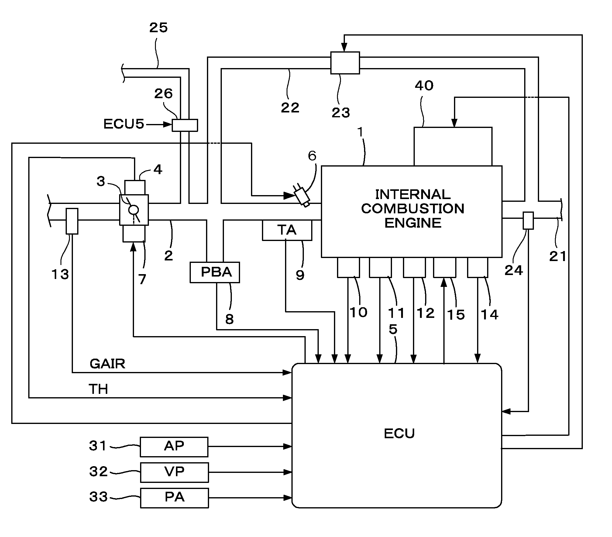
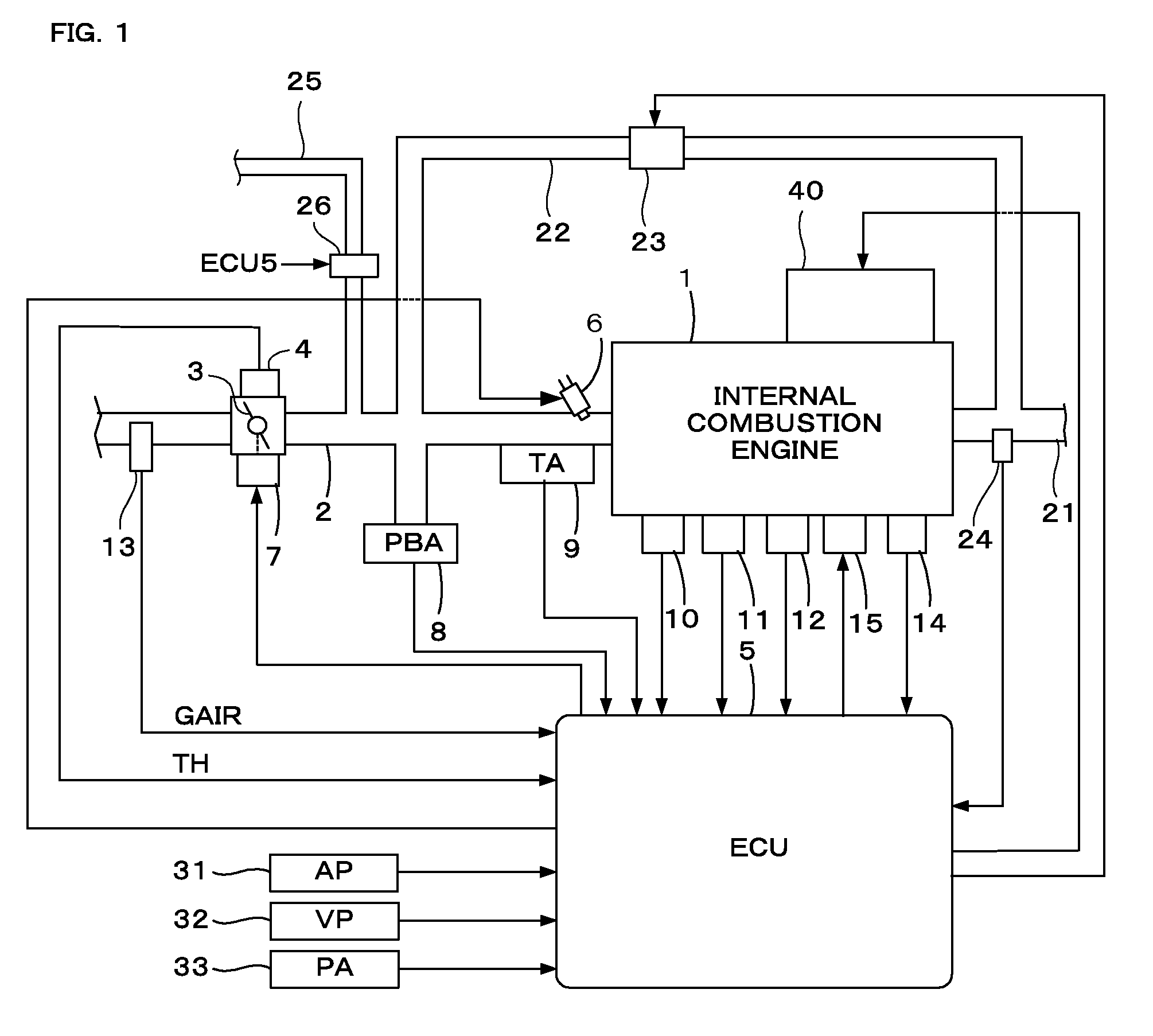
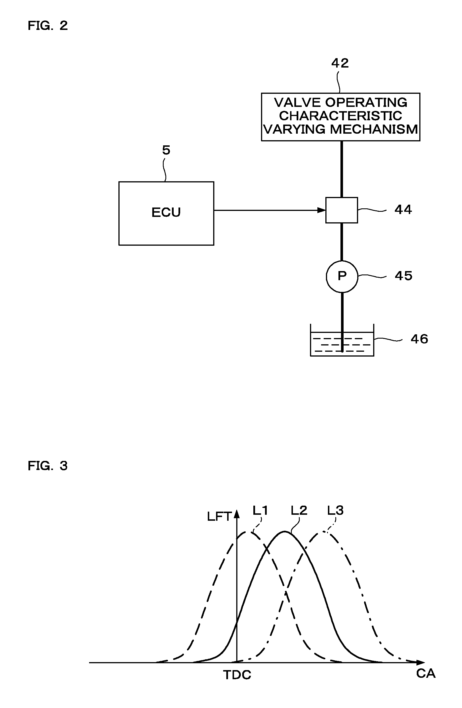
[0042]FIG. 1 is a schematic diagram showing a configuration of an internal combustion engine and a control apparatus therefor according to one embodiment of the present invention. FIG. 2 is a schematic diagram showing a configuration of a valve operating characteristic varying device. Referring to FIG. 1, an internal combustion engine (hereinafter referred to as “engine”) 1 having, for example, four cylinders is provided with intake valves, exhaust valves, and cams for driving the intake valves and the exhaust valves. The engine 1 is provided with a valve operating characteristic varying device 40 having a valve operating characteristic varying mechanism 42 as a cam phase varying mechanism for continuously varying the operating phase of the cams for driving the intake valves with reference to a rotational angle of the crank shaft of the engine 1. The valve operating characterist...


PUM


Abstract

A control apparatus for an internal combustion engine having a throttle valve disposed in an intake passage of the engine is provided. A wide-open intake air amount, which is an intake air amount corresponding to a state where the throttle valve is fully opened, is calculated, and a theoretical intake air amount, which is an intake air amount corresponding to a state where no exhaust gas of the engine is recirculated to a combustion chamber of the engine, is calculated according to the wide-open intake air amount and the intake pressure. An air-fuel ratio correction amount and a learning value thereof are calculated according to the detected air-fuel ratio, and a reference intake air amount is calculated using the intake pressure, the engine rotational speed, the air-fuel ratio correction amount, and the learning value. A lower limit value of the detected intake air amount is set according to the reference intake air amount, and a limit process is performed for limiting the detected intake air amount within a range of values which are equal to or greater than the lower limit value. An amount of the evaporative fuel / air mixture supplied to the intake passage is calculated, and the limit-processed intake air amount is corrected using the evaporative fuel / air mixture amount to calculate an intake gas amount. An exhaust gas recirculation ratio is calculated using the theoretical intake air amount and the intake gas amount.

Description

TECHNICAL FIELD[0001]The present invention relates to a control apparatus for an internal combustion engine, and particularly to the control apparatus for the internal combustion engine, which performs a control based on an exhaust gas recirculation ratio indicative of a ratio of exhaust gases (burnt gases) contained in the gases sucked into the combustion chamber of the engine.BACKGROUND ART[0002]Patent Document 1 (shown below) shows a method for calculating an exhaust gas recirculation ratio using an intake air amount sensor which detects an intake air amount of an engine. The detected intake air amount sometimes deviates from an actual intake air amount due to differences in the characteristic of the intake air amount sensor and other factors. According to the method shown in Patent Document 1, calculation accuracy of the exhaust gas recirculation ratio decreases if there is such deviation in the detected intake air amount.[0003]Patent Document 2 shows an air-fuel ratio control a...

Claims


Application Information

Patent Timeline
Patent Type & Authority Patents(United States)
IPC IPC(8): F02D37/02F02M25/08F02P5/152
CPCF02P5/152F02D2200/0402F02D41/0072F02M25/08F02D41/18Y02T10/46F02D41/0045Y02T10/47F02D41/0062F02D2200/0414F02M25/07F02D2041/001F02P5/1516F02D41/0042F02D41/0052F02D41/2445F02D41/2454F02M26/00Y02T10/40
Inventor IRIE, SEIICHIROITO, HISASHITAKAMIYA, HIDEHARUKOMATSU, HIROTAKAMOTOHASHI, YASUHIRO
Owner HONDA MOTOR CO LTD
Learn More