
Optically pumped magnetically controlled paramagnetic devices for microwave electronics and particle accelerator applications

a technology of paramagnetic devices and microwave electronics, applied in the field of microwave electronics, can solve the problems of inability to intrinsically, the use of existing materials with sufficiently large high field breakdown strength, and the limitations of the cost, size and weight of existing materials, etc., and achieve the effect of prohibitive cost of a conventional linear accelerator

Active Publication Date: 2014-12-30
EUCLID TECHLABS LLC +1
View PDF8 Cites 3 Cited by
  • Summary
  • Abstract
  • Description
  • Claims
  • Application Information

AI Technical Summary

Benefits of technology

The patent text describes a technology that can amplify or modify microwave signals using a magnetic control signal and optical pumping. This technology can be used to create versatile and compact electronic and accelerator devices. It has been shown that it can be used to create microwave amplifiers with adjustable properties using an external magnetic field, multi-pole active analog filter networks, and active metamaterials with refractive properties controllable using optical and magnetic means. The technical effects of this technology include improved performance and versatility of microwave devices and the ability to control the movement of energy in a way that was previously not possible.

Problems solved by technology

While it is possible to add components and circuitry to provide external control (via a magnetic field) or to energize the amplifier using and optical source of energy, these options are not intrinsically part of the amplifier.
In such embodiments, the use of existing materials with sufficiently large high field breakdown strength form limitations on the cost, size and weight.
Similarly, the mechanisms for generating the energy necessary to accelerate the particles as rapidly as possible also lead to large cost, weight, and space requirements.
This is particularly problematic for the use of accelerators as research instruments for universities or for applications at small or remote medical facilities.
Further, the size requirements of present technology accelerators preclude any portable applications, for example, for explosive or contraband material detection.
Further still, the lack of phase balance or other controls of the charged particle beam and the accelerating wave in such accelerators lowers the acceleration efficiency.

Method used


Image

  • Optically pumped magnetically controlled paramagnetic devices for microwave electronics and particle accelerator applications
  • Optically pumped magnetically controlled paramagnetic devices for microwave electronics and particle accelerator applications
  • Optically pumped magnetically controlled paramagnetic devices for microwave electronics and particle accelerator applications

Examples


Embodiment Construction

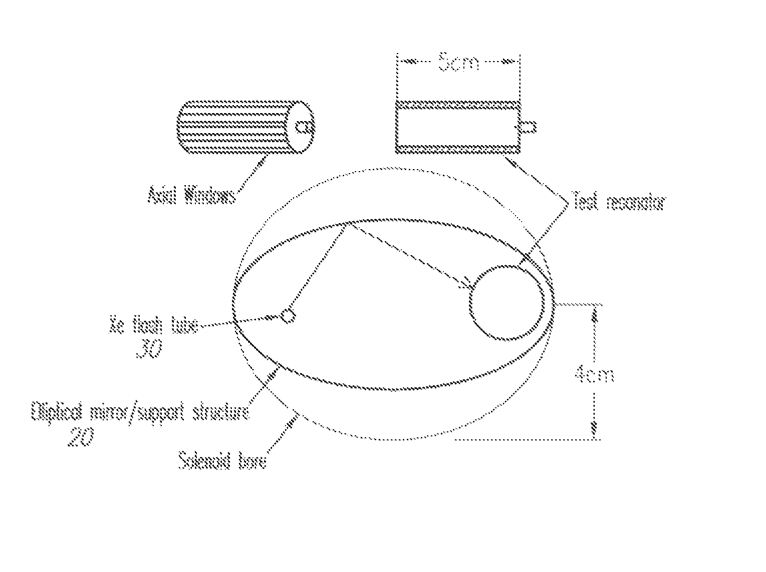
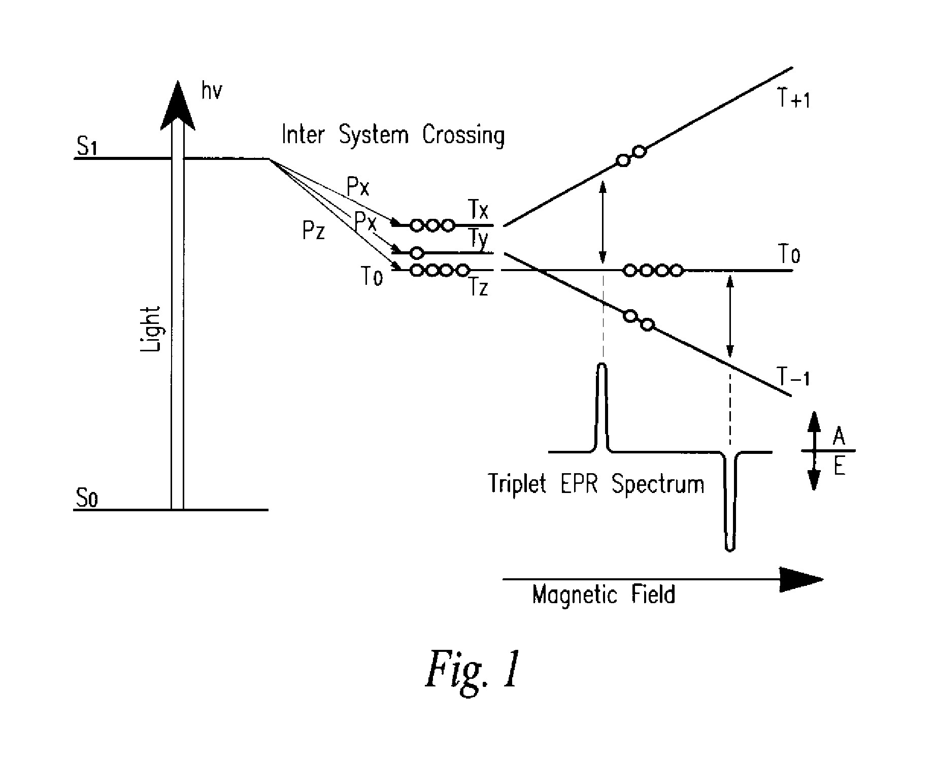
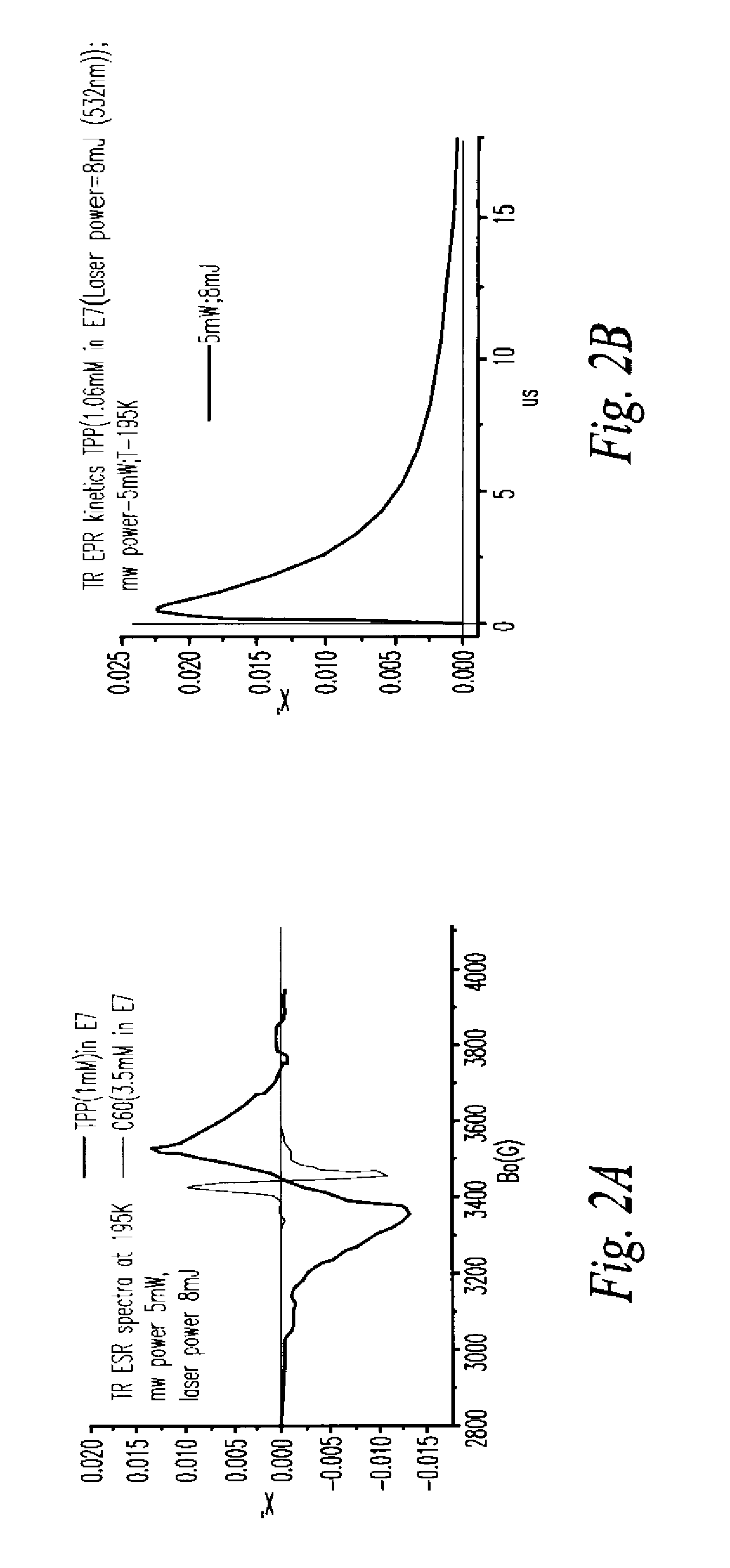
[0037]An active material is one in which a population inversion exists and thus can undergo stimulated emission of electromagnetic radiation. Equivalently, an active material has a negative imaginary part of its permittivity or permeability. In a paramagnetic active medium such as PCBM the imaginary part of the magnetic susceptibility χ″ is negative in some range of frequencies, i.e. the medium stores energy and can transfer this stored energy to an electronic circuit or charged particle beam. The possibility of a microwave device based on this technology was previously theoretically suggested by the existence of a large class of X-band and higher frequency paramagnetic active materials as observed via time resolved electron paramagnetic resonance (EPR) spectroscopy. These materials were found to retain activity at relatively high temperatures and possess reasonably high energy densities when pumped by an optical source such as a laser or flashlamp.

[0038]For particle accelerator app...


PUM


Abstract

An active device is provided that is energized by an optical source and uses an active paramagnetic medium to transfer this energy to a resonant circuit enabling new classes of electronic components.

Description

RELATED APPLICATIONS[0001]The present application claims benefit of U.S. Provisional Application 61 / 169,904 filed on Apr. 16, 2009 and incorporated by reference herein as if fully rewritten.BACKGROUND OF THE INVENTION[0002]1. Technical Field of the Invention[0003]The present invention is in the technical field of microwave electronics, in particular to microwave components (amplifiers and attenuators) in which an active paramagnetic material is energized by an optical source and transfers this energy to a resonant microwave circuit or resonant cavity. The characteristics of this device are controllable by an external magnetic field. A particular application of this technology is to power a compact linear particle accelerator that is energized by an optical source and utilizes an active paramagnetic medium to transfer this energy to a charged particle beam.[0004]2. Description of the Background Art[0005]Conventional microwave amplifiers use solid state or vacuum tube technology to ad...

Claims


Application Information

Patent Timeline
IPC IPC(8): G01R33/02G01R33/00
CPCG01R33/02H05H15/00G01N24/10G01R33/60
Inventor KANAREYKIN, ALEXEISCHOESSOW, PAULANTIPOV, SERGEYPOLUEKTOV, OLEG
Owner EUCLID TECHLABS LLC
Learn More