Anterior intervertebral spacer and integrated plate assembly and methods of use

an intervertebral spacer and integrated plate technology, applied in the field of sets of intervertebral spacer and integrated plate assemblies, can solve the problems of high subsidence, pain, compression and pain of spinal cord or nerve impingement, and achieve the effect of promoting spine stability and fusion

Inactive Publication Date: 2015-01-13
NEHLS DANIEL
View PDF19 Cites 65 Cited by
  • Summary
  • Abstract
  • Description
  • Claims
  • Application Information

AI Technical Summary

Benefits of technology

[0009]The vertebral plate and spacer assemblies of the present invention comprise a spacer that is size paired with an anterior plate, such that the once the surgeon selects the appropriate spacer size to fit tightly within a cylindrical hole based upon the diameter of the intervertebral drilling instruments (e.g. reamer and milling guide), then the plate is also selected (versus the surgeon trying to mix and match plates during surgery). Since the spacer also matches the diameter of the drilling instruments, it precisely fits within the intervertebral space to form a tight fit against the superior and inferior endplates to promote spine stability and fusion.
[0017]The U-shaped interbody spacer may further comprise a posterior side wall that rests against a “stop”, or shelf created by the surgeon drilling into endplates of the inferior and superior vertebral bodies near the posterior face of the bodies. The top and bottom edges of the external surface of the spacer posterior wall / plate rest against the anterior facing shelf to prevent slippage of the spacer posteriorly into the spinal canal.
[0019]Preferred anterior plates of the present invention comprise an essentially planar “H-shaped” vertebral plate comprising: 1) a “middle” member residing in the center of the plate (e.g. middle of the “H”); and, 2) two “outer” members extending from the opposing sides of the middle member. A multitude of suitable or similar shapes can alternatively be used. In one embodiment, the middle member is circular or oval; and, the outer members are rectangular or square. The middle (e.g. circular) member is size matched to fit the hole created by the surgeon when drilling into the disc during the discectomy; and, to fit the chamber (e.g. cylindrical) on the anterior end of the size matched U-shaped spacer. The rectangular members are also partially or nearly completely countersunk into a space created by the surgeon on the anterior surface of the intervertebral space. Therefore, only the anchor members and a small extension of the anterior surface of the spacer-plate assembly reside outside of the intervertebral space (i.e. the anterior side / surface of the rectangular shaped member and circular member reside primarily aligned with the anterior face of the intervertebral space). The low profile of the plate thus significantly reduces the risk of the patient developing dysphagia and other medical complications as a result of the implant protruding anteriorly from the intervertebral space.
[0022]In one embodiment, there are four square anchor members, one each positioned on each of the four corner ends of the outer member (one per each inferior and superior end of the H-shaped member), wherein each member has a tapered anterior profile so that it lays flush with its point of contact with the anterior face of the anterior plate. Each anchor member further comprises a fastener channel consisting of a hole within the center of an anchor member for threading a screw, or other fastener device, to secure the plate to the anterior cortex face of a superior or inferior vertebral body. The hole may thus possess helical threads to match and guide the screws. The anchor member is affixed to the junction created by the anterior cortex face and the intervertebral endplates of the vertebral bodies. The placement of the anchor members also permits the screws to be angled as compared to prior art anterior plates, i.e. horizontal aligned or substantially so, and resulting in the fastener devices being securely fixed into the cortical bone of the superior and inferior vertebral bodies versus the soft endplate.
[0024]The anterior plate in the assemblies may further comprise a hinged anterior plate as disclosed in U.S. Patent Application 20120065688 by Nehls, which is hereby expressly incorporated by reference herein in its entirety, and comprising a hinge member running laterally down the middle of the plate to allow the plate to flex, or angle towards the vertebral column at a limited angle so as to apply compressive loads to the spacer and thus enhance fusion of the superior and inferior vertebral bodies. The posterior surface of the hinge plate preferably comprises a circular member with a diameter matching the diameter of the hollow cylindrical cavity within the spacer. Therefore, when the posterior surface of the hinge plate is joined to the anterior surface of the spacer, it forms a tight seal to prevent rotation or shifting of the graft within the spacer. The hinge plate may further comprise male / female connectors to further secure the plate to the spacer comprising male members (e.g. cylindrical, rectangular, etc.) extending perpendicular and posteriorly from the posterior face of the hinge plate into female cavities residing on the anterior surface of the spacer. The male members can reside on the rectangular members of the plate and / or in the circular member. In the latter case, the female cavity resides in the center of the graft (e.g. bone dowel).

Problems solved by technology

Pressure from the vertebrae superior and inferior to the disc may cause the nucleus pulposus to be forced outward, placing pressure on a spinal nerve and causing considerable pain and damage to the nerve.
Unfortunately, cages have been shown to have result in a high degree of subsidence, wherein subsidence of the cage was defined as a decrease in total vertical height of the two fused vertebral bodies as measured on the lateral cervical radiographs made 3 and 6 months postoperatively compared with the directly postoperative radiographs.
Additionally, BMP has been labeled dangerous for use in ACDF by the US Food and Drug Administration because it may trigger swelling of neck tissues.
The spacer is held in place by the pressure of the superior and inferior vertebral bodies, and can easily migrate posteriorly into the spinal canal and cause compression and pain from impingement of the spinal cord or nerves.
This approach also has disadvantages in that attachment to the vertebral endplates is not as strong as attachment to the hard anterior cortex of the vertebrae, as seen in flat plates.
But, this method can be disadvantageous as these plates are generally not low-profile, resulting in post-operative dysphagia, and recurrent laryngeal nerve palsy (Fountas K N, et al.
ACDF plates also tend to be long and may encroach upon the space of an adjacent disc space or vertebral body, which may lead to disc degeneration.
This is a tedious and cumbersome procedure to perform during surgery.

Method used


Image

  • Anterior intervertebral spacer and integrated plate assembly and methods of use
  • Anterior intervertebral spacer and integrated plate assembly and methods of use
  • Anterior intervertebral spacer and integrated plate assembly and methods of use

Examples


Embodiment Construction

[0045]Embodiments of the present invention are described below with reference to the above described Figures. It is, however, expressly noted that the present invention is not limited to the embodiments depicted in the Figures, but rather the intention is that modifications that are apparent to the person skilled in the art and equivalents thereof are also included.

Intervertebral Plate-Spacer Assembly

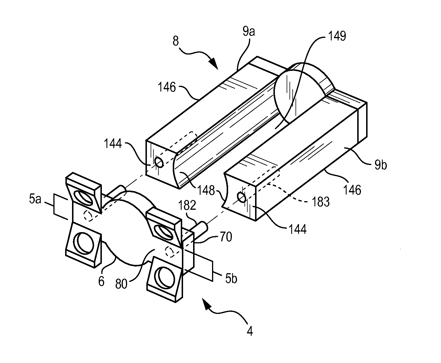
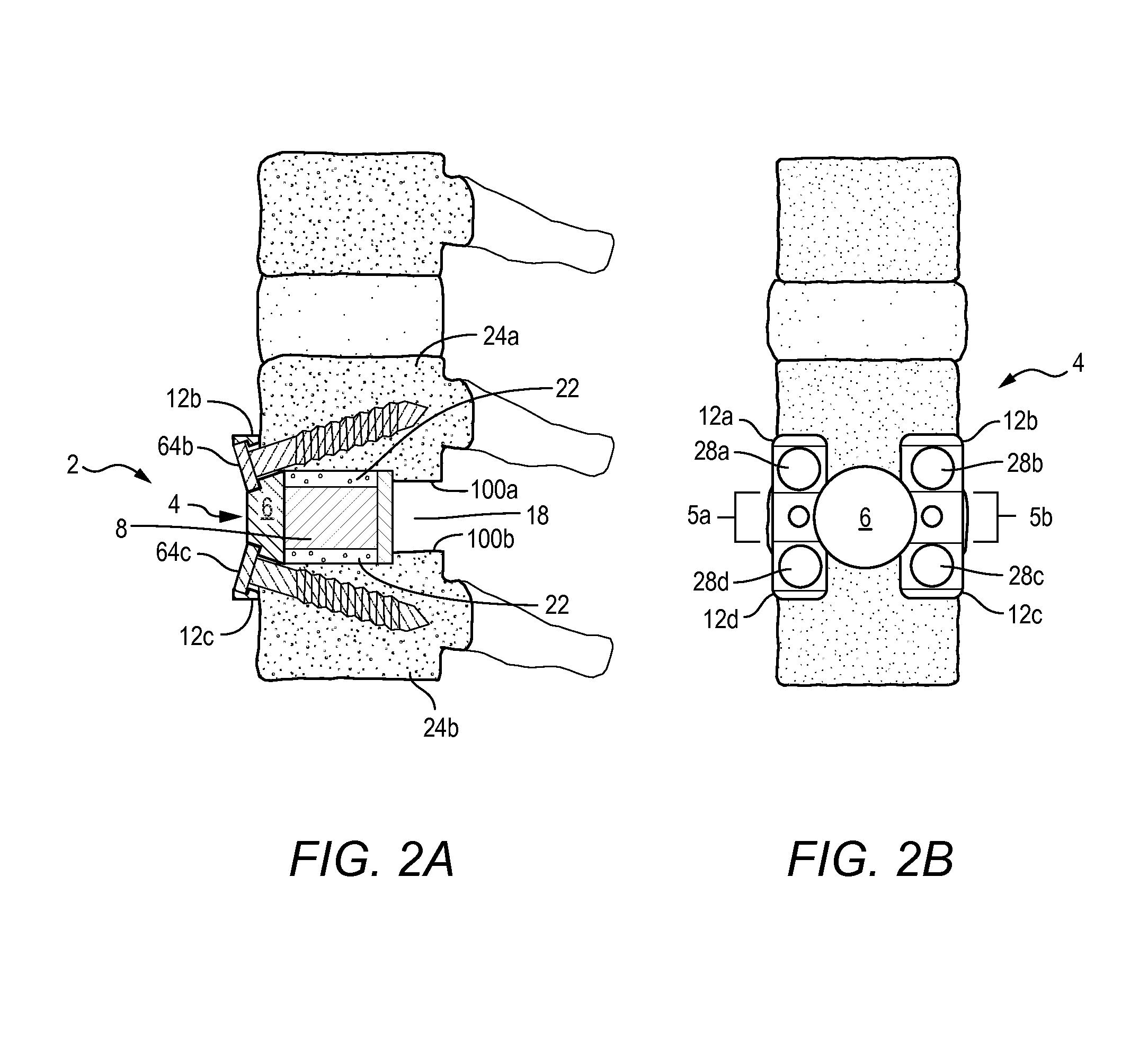
[0046]The following disclosure is for one embodiment exemplified in the figures comprising a plate with a circular middle member and rectangular outer members. And unless stated otherwise, the term “intervertebral plate and spacer assembly”2 as used herein generally relates to spinal implants comprising an H-shaped anterior plate, whether hinged or non-hinged, that is size matched to a hollow U-shaped cylindrical spacer, wherein the spacer may or may not comprise a superior and inferior wall. All Figures herein demonstrate an embodiment of the assembly comprising a spacer that lacks a s...


PUM


Abstract

A precisely size matched intervertebral plate and spacer assembly for ensuring a tight fit within a disc space to promote spinal fusion, comprising: a “U-shaped” spacer configured to fit within the intervertebral space; and, a matching countersunk low profile “H-shaped” anterior plate joined perpendicularly to the spacer. The plate further comprises: a plurality of anchor members configured to attach to the junctions of the anterior cortex faces and the endplates; and, channels individually traversing through the anchor members for inserting screws into the vertebral bodies' cortical bone. The spacer comprises a hollow three-sided U-shaped member, comprising two opposing parallel side walls, and a perpendicular posterior wall, while lacking a superior, inferior, and anterior wall. The exterior walls of the plate and spacer are planar, while the interior walls of the spacer are curved to house a precisely fitting cylindrical graft, or other insert such as DBM, bone dust, bone paste, bone dowel with direct contact to the endplates to promote fusion.

Description

FIELD OF THE INVENTION[0001]The embodiments herein relate to sets of intervertebral spacer and integrated plate assemblies and methods of use in spinal fixation procedures. More particularly, the teachings herein relate to improving current methods and systems directed to fusing one or more adjacent vertebral bodies within the cervical spine.BACKGROUND[0002]A human spine comprises 33 vertically aligned bone structures termed “vertebrae” or “vertebral bodies”: 7 cervical, 12 thoracic, 5 lumbar, 5 sacral (fused into one bone, the sacrum), and 4 coccygeal (fused into one bone, the coccyx). Each vertebral body comprises a cylindrical structure composed of hard cortical bone on the outside and less dense cancellous bone on the inside, while the inferior and superior sides of each vertebral body are layered with end plates that are typically about 1 mm thick and comprise both bone and hyaline cartilage. Between each vertebral body is a flexible, connective tissue termed an “intervertebral...

Claims


Application Information

Patent Timeline
Patent Type & Authority Patents(United States)
IPC IPC(8): A61F2/44
CPCA61F2/442A61F2/30744A61F2/4455A61F2002/2835A61F2002/30331A61F2002/30383A61F2002/305A61F2002/30578A61F2002/30787
Inventor NEHLS, DANIEL
Owner NEHLS DANIEL
Why Eureka
Try Eureka