Environmental barrier for a refractory substrate containing silicon

a technology of environment barrier and refractory substrate, which is applied in the direction of wind motor components, non-positive displacement fluid engines, liquid fuel engine components, etc., can solve the problems of significant degradation, difficult to envisage above use, and oxidation into silica, so as to achieve the effect of conserving its effectiveness

Active Publication Date: 2015-01-27
UNIV DE BORDEAUX I +1
View PDF16 Cites 17 Cited by
  • Summary
  • Abstract
  • Description
  • Claims
  • Application Information

AI Technical Summary

Benefits of technology

[0014]In a first aspect, an object of the invention is to provide a method of protecting a substrate in which at least a portion adjacent to a surface is made of a refractory material containing silicon, by forming an environmental barrier that is capable of conserving its effectiveness in an atmosphere that is oxidizing and wet, and up to at least 1400° C., including in the presence of a gas stream at high speed.
[0016]The presence of at least one solid phase at the self-healing temperature increases the ability to withstand being blown away.
[0017]The term “self-healing temperature” is used herein to mean a temperature at which a liquid phase is formed in a quantity that is sufficient to provide the self-healing function, i.e. at least 5 mol % in the composition of the self-healing layer, in order to be effective in plugging any cracks that might appear, but without exceeding 40 mol % in said composition in order to provide good resistance to being blown away.
[0018]Advantageously, an environmental barrier is formed that also includes an underlayer that is interposed between the surface of the substrate and the self-healing layer, and that remains in the solid state at the self-healing temperature. This avoids exposing the surface of the substrate directly to the liquid phase of the self-healing layer.

Problems solved by technology

Satisfactory behavior for that environmental barrier has been observed at temperatures of up to 1200° C. approximately, but significant degradation is observed when the temperature exceeds 1300° C. Indeed, the bonding layer made of silicon or the surface of the matrix of the substrate material containing silicon is easily oxidized into silica in the event of cracks or defects, such as flakes, being created in the environmental barrier while the material is in use.
The indicated maximum operating temperature is 1400° C. Nevertheless, it should be observed that the melting of the coating at 1375° C. makes it difficult to envisage use above that temperature, in particular when the surface is exposed to a stream of gas at high speed, since it is then possible for the coating to be blown away.

Method used


Image

  • Environmental barrier for a refractory substrate containing silicon
  • Environmental barrier for a refractory substrate containing silicon
  • Environmental barrier for a refractory substrate containing silicon

Examples


example 1

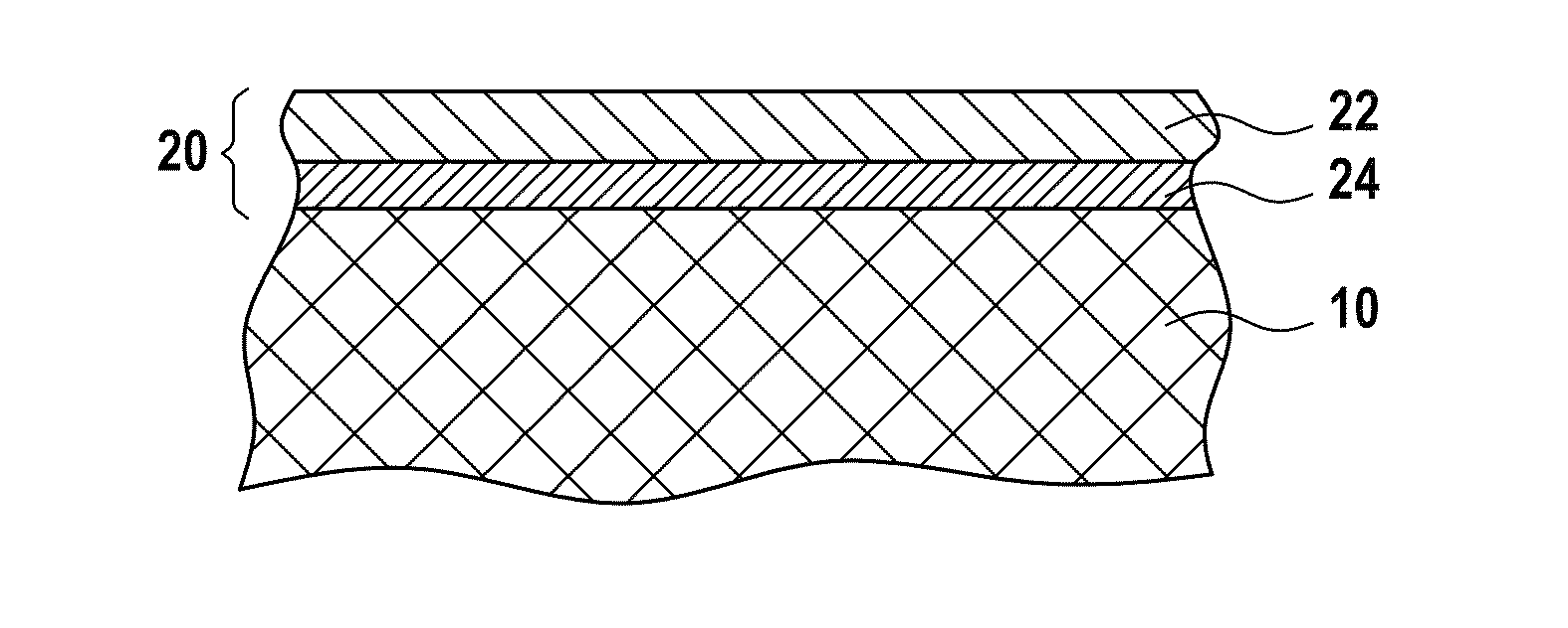
[0050]An SiC / SiC composite material substrate comprising fiber reinforcement made of SiC fibers and an SiC matrix, was provided with an environmental barrier as follows:[0051]depositing an underlayer of yttrium silicate Y2Si2O7 from an Y2Si2O7 powder onto the SiC / SiC substrate by plasma spraying, the underlayer having a thickness of about 200 μm; and[0052]depositing an outer layer on the underlayer by plasma spraying, starting from a mixture of powders of mullite (15 mol %) and of Y2Si2O7 (85 mol %) giving a composition that formed a system of Y2O3 (53.61 weight percent (wt %)), SiO2 (33.57 wt %), and Al2O3 (12.82 wt %), with the thickness of the outer layer being about 100 μm.

[0053]At 1400° C. and at 1450° C. the outer layer possessed a liquid phase capable of sealing cracks that appear in the environmental barrier, and having two solid phases at 1400° C. and one solid phase at 1450° C.

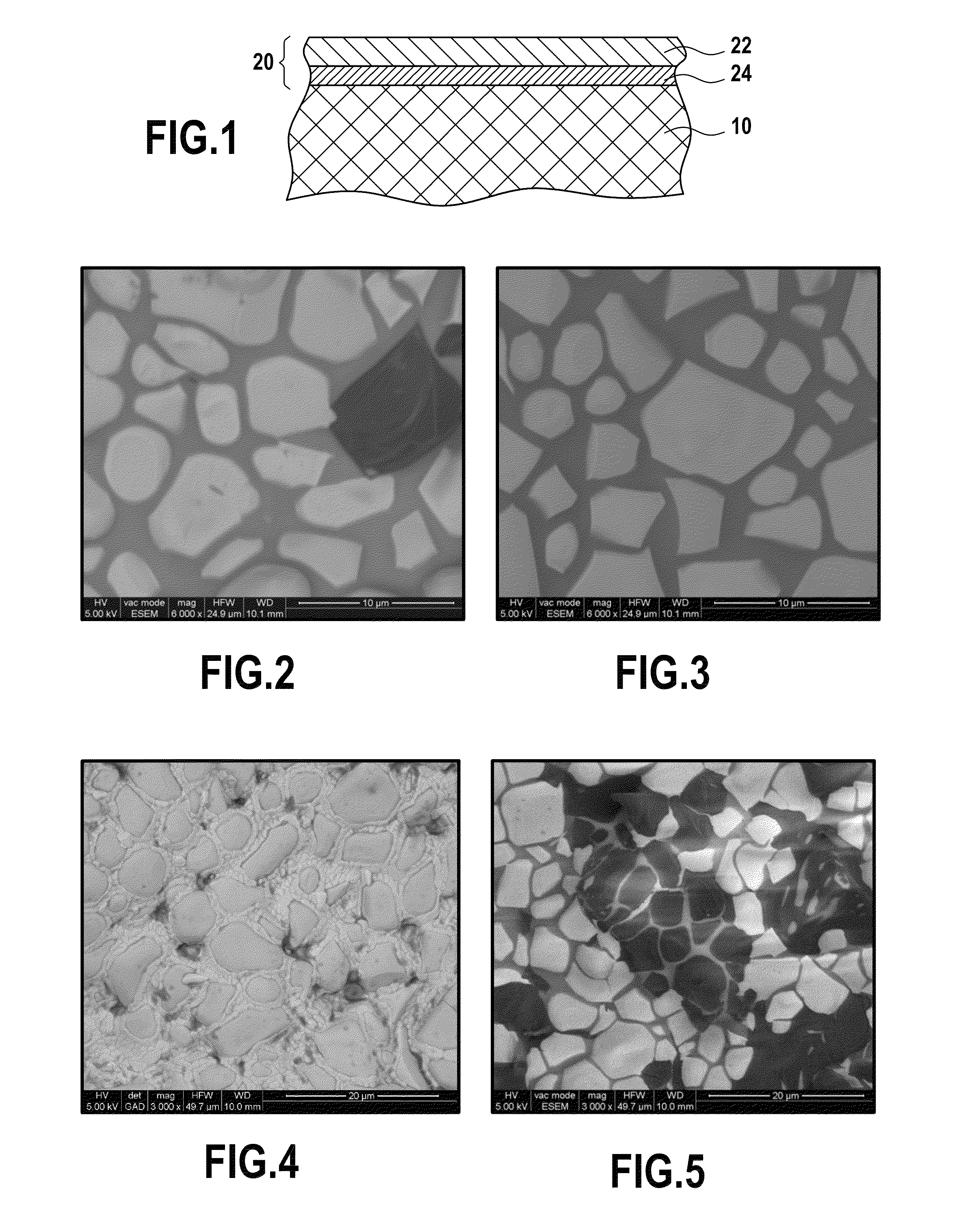
[0054]FIG. 2 shows a portion of the surface of the outer layer after its temperature had been rai...

example 2

[0056]The procedure was as in Example 1, but the outer layer was formed from a mixture of powders of mullite (41.2 mol %) and of Y2Si2O7 (58.8 mol %), giving a composition forming the following system: Y2O3 (35.04 wt %), SiO2 (31.71 wt %), and Al2O3 (33.25 wt %).

[0057]FIG. 5 shows a portion of the surface of the outer layer after 50 h under air at 1400° C. The liquid phase identical to that of Example 1 occupies all of the space between the grains of Y2Si2O7 (white) and of mullite and of Al2O3 (black), thereby providing self-healing. In the composition of the outer layer, the liquid phase represented about 5 mol % to 8 mol %.

[0058]It should be observed that at 1450° C., the outer layer melted, with the quantity of liquid phase becoming excessive.

example 3

[0059]The procedure was as in Example 1, but the outer layer was formed from a mixture of powders of mullite (54.4 mol %) and of Y2Si2O7 (45.6 mol %), giving a composition forming the following system: Y2O3 (26.43 wt %), SiO2 (30.85 wt %), and Al2O3 (42.72 wt %).

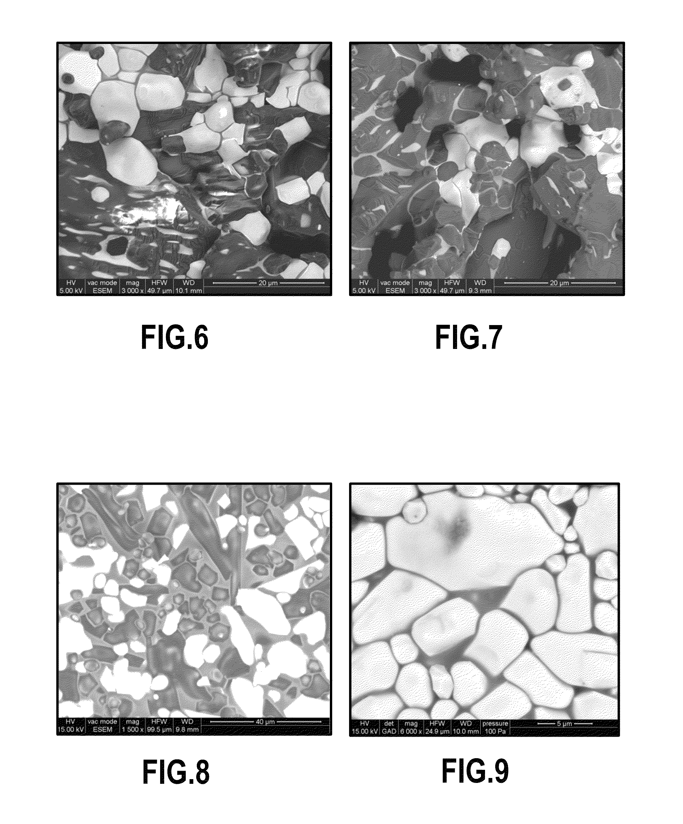
[0060]FIG. 6 shows a portion of the surface of the outer layer after 50 h in air at 1400° C. A liquid phase identical to that of Example 1 was indeed formed, but the quantity of liquid phase was insufficient, so that pores remained. Self-healing therefore could not be achieved completely. In the composition of the outer layer, the liquid phase represented significantly less than 5 mol %.

[0061]At 1450° C., the outer layer had melted, with the quantity of liquid becoming excessive.


PUM

PropertyMeasurementUnit
temperatureaaaaaaaaaa

Abstract

In order to protect a substrate having at least a portion adjacent to a surface that is made of a refractory material containing silicon, while the substrate is in use at high temperature in a medium that is oxidizing and wet, there is formed on the surface of the substrate an environmental barrier that contains no boron and that has at least one layer that is essentially constituted by a system of oxides formed by at least one rare earth oxide, silica, and alumina, and that is capable of self-healing by maintaining the presence of at least one solid phase in a temperature range extending up to at least 1400° C. approximately.

Description

CROSS REFERENCE TO RELATED APPLICATIONS[0001]This application is the U.S. National Stage of PCT / FR2009 / 052672 filed Dec. 23, 2009, which in turn claims priority to French Application No. 0859076, filed Dec. 24, 2008. The contents of both applications are incorporated herein by reference in their entirety.BACKGROUND OF THE INVENTION[0002]For a substrate in which at least a portion adjacent to a surface is made of a refractory material containing silicon, the invention relates to protecting the substrate while it is being used at high temperature in a medium that is oxidizing and wet, by forming on the surface of the substrate an environmental barrier that does not contain boron.[0003]The invention seeks in particular to protect refractory materials constituted by monolithic ceramics, e.g. silicon carbide SiC or silicon nitride Si3N4, and more particularly to protect refractory composite materials such as ceramic matrix composite (CMC) materials containing silicon, e.g. CMCs having a ...

Claims


Application Information

Patent Timeline
Patent Type & Authority Patents(United States)
IPC IPC(8): B63H1/26B32B9/04B32B9/00B32B19/00C04B35/18C04B35/185C04B41/00C04B41/52C04B41/89C23C4/10C23C28/04C23C30/00F01D5/28
CPCC04B41/89C04B35/18C04B35/185C04B41/009C04B41/52C23C4/105C23C30/00F01D5/288C23C28/042C23C28/048C04B41/5096C04B41/4527C04B41/5024C04B41/5037C04B41/522C04B35/565C04B35/584C04B35/806C04B2235/3222C04B2235/3225C04B2235/3427C04B2235/3463C04B2235/80Y02T50/67Y02T50/672C23C4/11Y02T50/60
Inventor COURCOT, EMILIEREBILLAT, FRANCISLOUCHET-POUILLERIE, CAROLINETAWIL, HENRI
Owner UNIV DE BORDEAUX I
Why Eureka
Try Eureka