
Semiconductor light source lighting circuit

a technology of semiconductors and light sources, applied in the direction of electric variable regulation, process and machine control, instruments, etc., can solve the problems of capacitor loss, capacitor overshoot, capacitor overshoot, etc., to suppress the overshoot or undershoot of the drive current

Active Publication Date: 2015-02-03
KOITO MFG CO LTD
View PDF21 Cites 16 Cited by
  • Summary
  • Abstract
  • Description
  • Claims
  • Application Information

AI Technical Summary

Benefits of technology

The patent describes a circuit that helps to prevent the drive current of a semiconductor light source from hitting a peak too high or too low. This circuit can help to improve the stability of the light source and make it more reliable.

Problems solved by technology

The former method has a color shift problem that the hue or the color temperature may vary depending on the current value.
However, in general, the capacitor has a loss and hence the voltage held by the capacitor varies gradually.
When the input voltage of a lighting control circuit or the number of LEDs to be driven is changed suddenly, the error amount in a current feedback loop may not be able to respond to such a sudden change properly, possibly resulting in an overshoot or undershoot of the LED current.

Method used


Image

  • Semiconductor light source lighting circuit
  • Semiconductor light source lighting circuit
  • Semiconductor light source lighting circuit

Examples


Embodiment Construction

[0023]Hereinafter, the same or equivalent components, members, and signals, which are shown in the respective drawings, are denoted by the same reference numerals, and the repeated description thereof will be appropriately omitted. Further, some of members, which are not important in the description, will be omitted in the respective drawings.

[0024]In the following, the same or equivalent constituent elements, members, or signals shown in the drawings are given the same reference symbol and redundant descriptions will be avoided where appropriate. In the drawings, part of members that are not important for descriptions may be omitted. Symbols that denote voltages, currents, resistors, etc. may also be used as representing voltage values, current values, resistance values, etc. when necessary.

[0025]In this specification, a phrase “a state that a member A is connected to a member B” means not only a case that the member A is connected to the member B physically and directly but also a...


PUM


Abstract

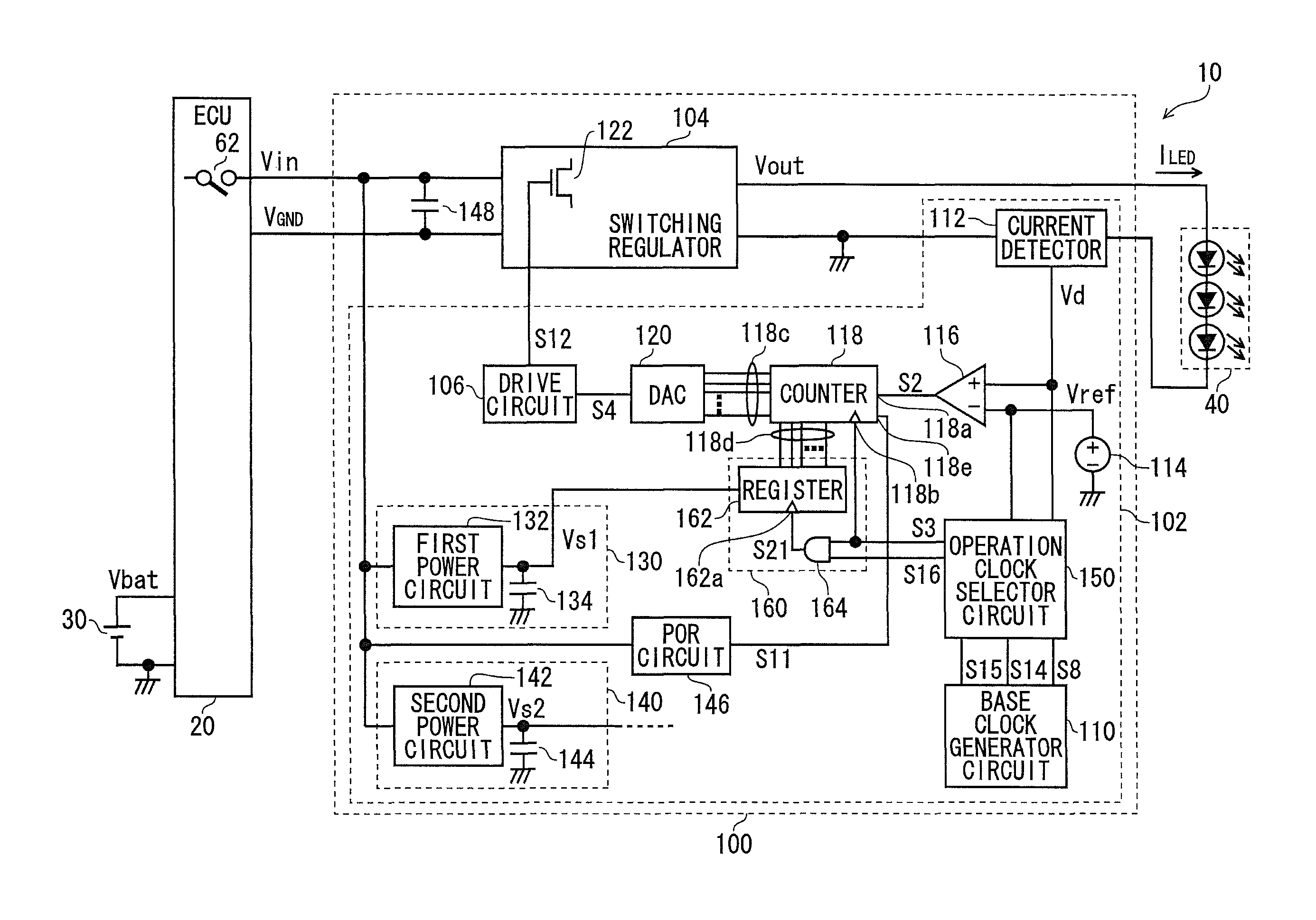
A circuit for lighting a semiconductor light source is provided. The circuit includes: a switching regulator including a switching element and configured to generate a drive current for the semiconductor light source using the switching element; and a control circuit configured to control on-off of the switching element such that the magnitude of the drive current comes close to a targeted value. The control circuit includes: a comparator configured to compare the magnitude of the drive current with the targeted value; an up / down counter configured to count a digital value in a counting-up direction or counting-down direction, based on a comparison result of the comparator; a digital-to-analog converter configured to convert the counted digital value into an analog signal; and a drive circuit configured to control on / off of the switching element based on the analog signal.

Description

[0001]This application claims priority from Japanese Patent Application No. 2011-221891, filed on Oct. 6, 2011, the entire contents of which are hereby incorporated by reference.BACKGROUND[0002]1. Technical Field[0003]The present invention relates to a semiconductor light source lighting circuit for turning on a semiconductor light source such as an LED (light-emitting diode).[0004]2. Related Art[0005]In recent years, LEDs which have longer life and lower power consumption than conventional halogen lamps which use filaments have come to be used in vehicular lamps such as headlights in place of halogen lamps. The degree of light emission, that is, the brightness, of the LED strongly depends on the current flowing through it. Therefore, to use LEDs as a light source, a lighting circuit for adjusting the current flowing through the LEDs is necessary. Usually, such a lighting circuit has an error amplifier and performs a feedback control so as to keep the current flowing through the LED...

Claims


Application Information

Patent Timeline
Patent Type & Authority Patents(United States)
IPC IPC(8): H05B37/02H05B44/00
CPCH05B33/089H05B33/0815H05B45/50H05B45/3725H05B45/56
Inventor KIKUCHI, SATOSHISHIOTSU, FUMINORINAMBA, TAKANORIITO, MASAYASU
Owner KOITO MFG CO LTD
Learn More