Methods for increasing a retention force between a polymeric scaffold and a delivery balloon

a polymer scaffold and delivery balloon technology, applied in the field of drugeluting medical devices, can solve the problems of unreliable several methods/models used to predict the behavior of metallic stents, complex interactions, and insufficient understanding of the mechanism of action, so as to achieve the effect of reducing the diameter of the delivery balloon and increasing the retention force of the crimped polymer scaffold

Active Publication Date: 2015-02-24
ABBOTT CARDIOVASCULAR
View PDF42 Cites 9 Cited by
  • Summary
  • Abstract
  • Description
  • Claims
  • Application Information

AI Technical Summary

Benefits of technology

[0013]It has been found that the retention force of a crimped polymer scaffold on delivery balloon may be increased by a process that includes crimping the scaffold to the balloon while the balloon is pressurized; that is, the balloon is pressurized at the same time as the scaffold's diameter is being reduced by crimper blades. Additional features of the crimping process include heating the scaffold to a temperature close to, but below the glass transition temperature (TG) of the polymer material and applying balloon pressure during dwell periods (i.e., balloon pressure is applied when the scaffold diameter is held constant).
[0021]According to another aspect of the invention, a method for crimping a balloon-expanded scaffold to a balloon includes the steps of providing a tube comprising PLLA characterized by a glass transition temperature range having a lower limit of about TG-low; radially expanding the tube to increase its radial stiffness; forming the scaffold from the radially-expanded tube, including the steps of forming a circumferential series of closed cells having a W-shape and linear link struts connecting the W-shape cells; and crimping the scaffold to the balloon while the scaffold has a crimping temperature of between about 5 to 15 degrees below TG-low including maintaining a pressure in the balloon as the scaffold diameter is being reduced in size.

Problems solved by technology

These interactions are complex and the mechanisms of action not fully understood.
Indeed, several of the accepted analytic or empirical methods / models used to predict the behavior of metallic stents tend to be unreliable, if not inappropriate, as methods / models for reliably and consistently predicting the highly non-linear behavior of a polymeric load-bearing portion of a balloon-expandable scaffold (hereinafter “scaffold”).
The models are not generally capable of providing an acceptable degree of certainty required for purposes of implanting the scaffold within a body, or predicting / anticipating the empirical data.
Moreover, it is recognized that the state of the art in medical device-related balloon fabrication, e.g., non-compliant balloons for scaffold deployment and / or angioplasty, provide only limited information about how a polymeric material might behave when used to support a lumen within a living being via plastic deformation of a network of rings interconnected by struts.
The scaffolding also tends to be brittle or have limited fracture toughness.
Processing steps performed on, design changes made to a metal stent that have not typically raised concerns for, or require careful attention to unanticipated changes in the average mechanical properties of the material, therefore, may not also apply to a scaffold due to the non-linear and sometimes unpredictable nature of the mechanical properties of the polymer under a similar loading condition.
It is recognized, therefore, that, whereas inferences previously accepted in the art for stent validation or feasibility when an isotropic and ductile metallic material was used, such inferences would be inappropriate for a scaffold.
This means that, in comparison to a metallic stent, there is generally no assumption that can be made as to whether a changed scaffold pattern may not produce an adverse outcome, or require a significant change in a processing step (e.g., tube forming, laser cutting, crimping, etc.).
A change in the pattern of the struts and rings of a scaffold that is plastically deformed, both when crimped to, and when later deployed by a balloon, unfortunately, is not as easy to predict as a metal stent.
Indeed, it is recognized that unexpected problems may arise in scaffold fabrication steps as a result of a changed pattern that would not have necessitated any changes if the pattern was instead formed from a metal tube.
One problem frequently encountered with a scaffold for delivery to a site in a body using a balloon is reliably retaining the scaffold on the balloon as it passes through tortuous anatomy.
If the scaffold is not held on the balloon with sufficient force, it can slip off of the balloon during transit to the target site.

Method used


Image

  • Methods for increasing a retention force between a polymeric scaffold and a delivery balloon
  • Methods for increasing a retention force between a polymeric scaffold and a delivery balloon
  • Methods for increasing a retention force between a polymeric scaffold and a delivery balloon

Examples


examples

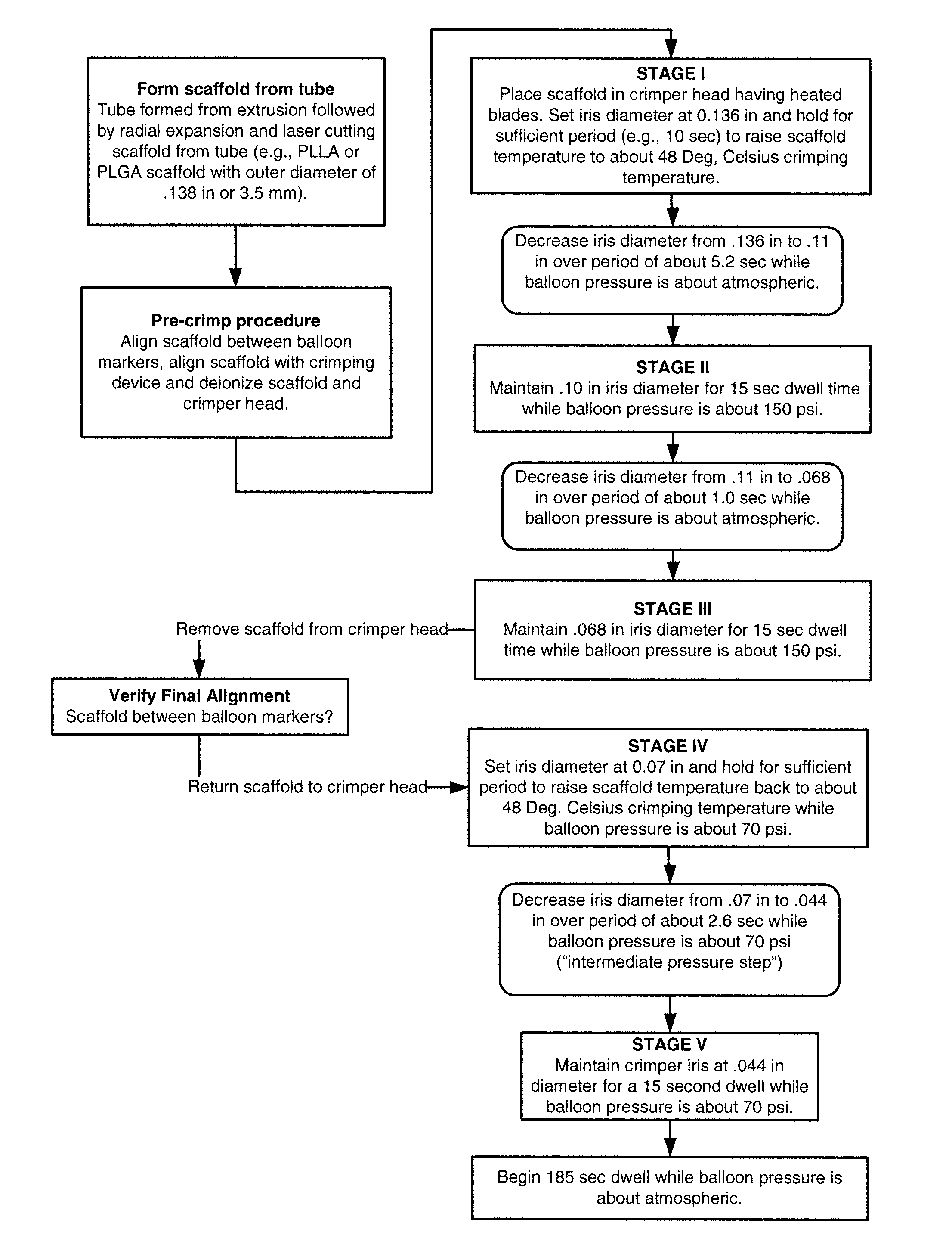
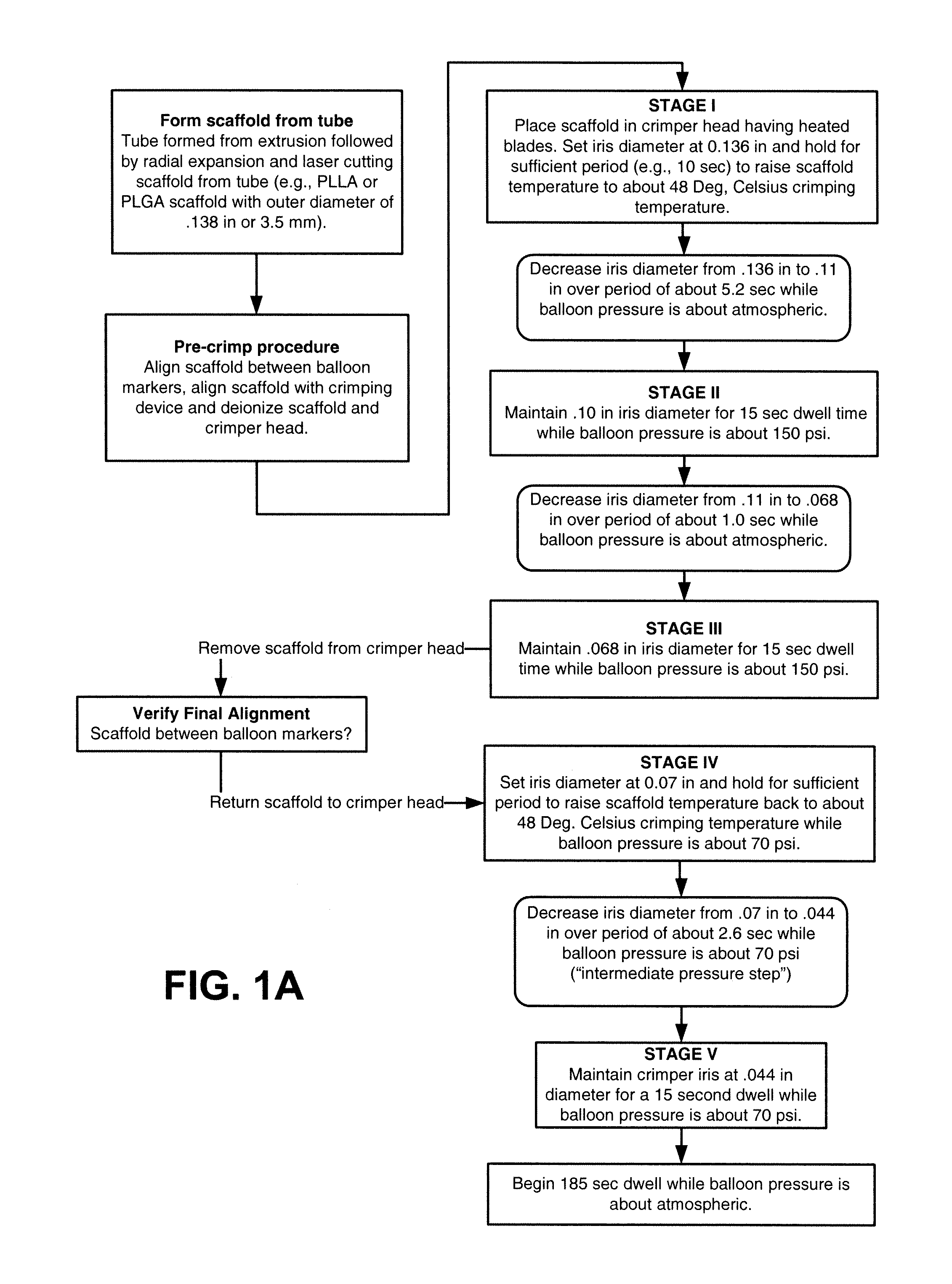
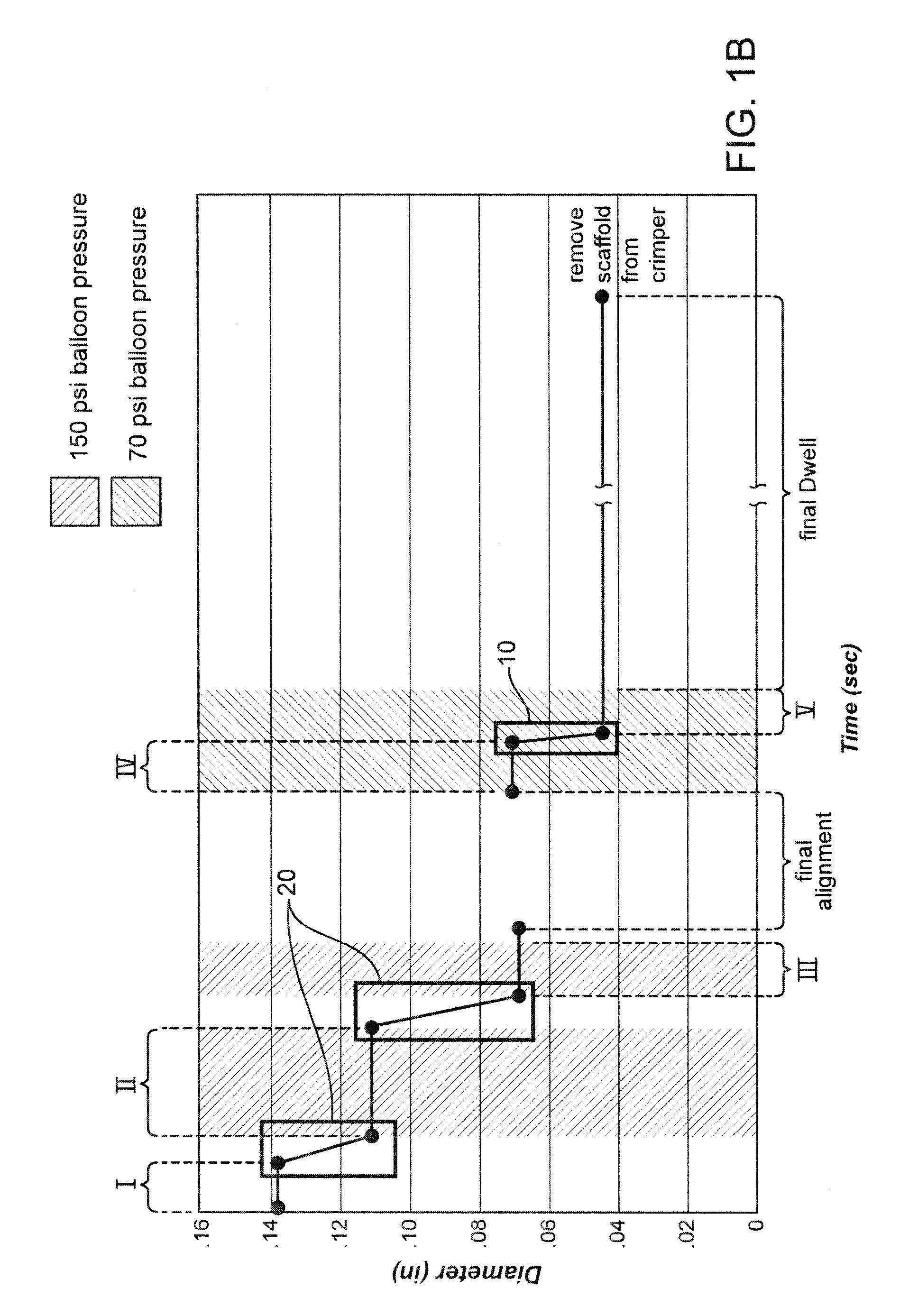
[0053]Further details of the FIG. 1A flow process for a 3.5 mm scaffold manufacture and crimping to a delivery balloon will now be discussed. FIG. 1B illustrates in graphical form the crimping portion of the FIG. 1A flow—a graph of scaffold diameter verses time with a balloon pressure of 150 psi or 70 psi applied during the dwell periods and the intermediate pressure step (i.e., crimping between Stage IV and Stage V). The scaffold was crimped using a crimper having film-sheets disposed between the metal crimper blades and the scaffold. This particular type of crimper is discussed in greater detail below.

[0054]As discussed above, the scaffold is formed from a PLLA or PLGA precursor, including a biaxial expansion of the precursor to form a tube, followed by laser cutting the scaffold from the tube. Next, a pre-crimp procedure is performed, which includes placing the scaffold between the balloon markers and aligning the scaffold with the iris of the crimper. Using an anti-static air gu...


PUM

PropertyMeasurementUnit
crimping temperatureaaaaaaaaaa
lengthaaaaaaaaaa
diameteraaaaaaaaaa

Abstract

A medical device-includes a scaffold crimped to a catheter having an expansion balloon. The scaffold is crimped to the balloon by a process that includes inflating the delivery balloon during a diameter reduction to improve scaffold retention and maintaining an inflated balloon during the diameter reduction and prior and subsequent dwell periods.

Description

BACKGROUND OF THE INVENTION[0001]1. Field of the Invention[0002]The present invention relates to drug-eluting medical devices; more particularly, this invention relates to processes for crimping a polymeric scaffold to a delivery balloon.[0003]2. Background of the Invention[0004]The art recognizes a variety of factors that affect a polymeric scaffold's ability to retain its structural integrity when subjected to external loadings, such as crimping and balloon expansion forces. These interactions are complex and the mechanisms of action not fully understood. According to the art, characteristics differentiating a polymeric, bio-absorbable scaffolding of the type expanded to a deployed state by plastic deformation from a similarly functioning metal stent are many and significant. Indeed, several of the accepted analytic or empirical methods / models used to predict the behavior of metallic stents tend to be unreliable, if not inappropriate, as methods / models for reliably and consistentl...

Claims


Application Information

Patent Timeline
Patent Type & Authority Patents(United States)
IPC IPC(8): B29C65/56
CPCB29L2031/7543B29L2028/00A61F2/958B29C65/66B29C66/532B29C66/63B29C66/71B29C66/73117B29C66/73791B29C66/92445B29C66/949B29C67/0014B29C55/24B29C65/7817B29C66/91945B29C2793/0009A61F2/915A61F2002/9583A61F2250/0067A61F2/2436B29C66/91411B29C66/91421B29C66/9292B29C66/92921A61F2/9522A61F2/9524B29K2067/046B29K2067/043A61L31/00B29B11/04B29K2101/00B29L2031/7534
Inventor ROBERTS, LILY AYOMCNIVEN, SEAN A.YAN, KATHLEENKNOTT, BOYD V.BEER, JEREMY B.JOHNSON, MARK C.
Owner ABBOTT CARDIOVASCULAR
Why Eureka
Try Eureka