
Methods and systems for generating power from a turbine using pressurized nitrogen

a technology of compressed nitrogen and turbine power, which is applied in the direction of greenhouse gas reduction, emission prevention, and flue gas purification components, can solve the problems of reducing the efficiency of steam-driven turbines, and reducing the cost of compressed nitrogen compression, so as to improve the efficiency of existing steam cycles and efficiently generate power. , the effect of smoothing out the power demand of the power grid

Active Publication Date: 2015-02-24
U S BANK TRUST CO NAT ASSOC
View PDF20 Cites 5 Cited by
  • Summary
  • Abstract
  • Description
  • Claims
  • Application Information

AI Technical Summary

Benefits of technology

The present disclosure describes methods and systems for using nitrogen in a turbine to generate power. The nitrogen is provided from an air separation unit in a liquid state and is then expanded in the turbine to generate power. The expanded nitrogen is then vented to the ambient air. This process allows for increased efficiency and the use of nitrogen as a stored energy source for smoothing power demands on power grids. Additionally, the invention is efficient in generating power from pressurized nitrogen, reducing the amount of water needed in the power plant. The system integrates power generation with air separation, resulting in efficiencies that cannot be obtained by optimizing the discrete systems separately.

Problems solved by technology

Thus, for a closed-loop system, the use of nitrogen to drive a turbine costs more than a comparable steam driven turbine.
Therefore, the compression of the gaseous nitrogen is a sunk cost associated with air separation.

Method used


Image

  • Methods and systems for generating power from a turbine using pressurized nitrogen
  • Methods and systems for generating power from a turbine using pressurized nitrogen

Examples


Embodiment Construction

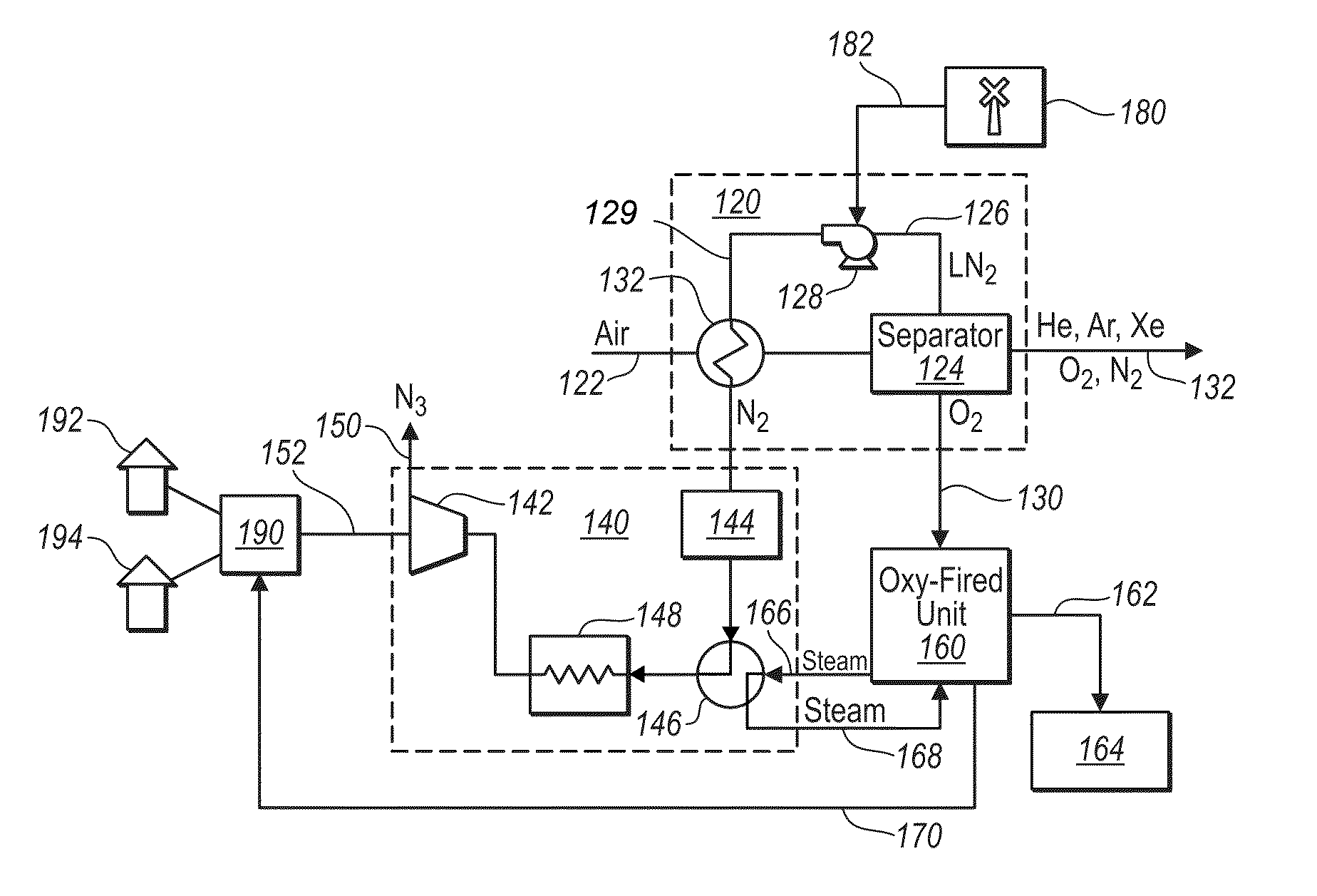
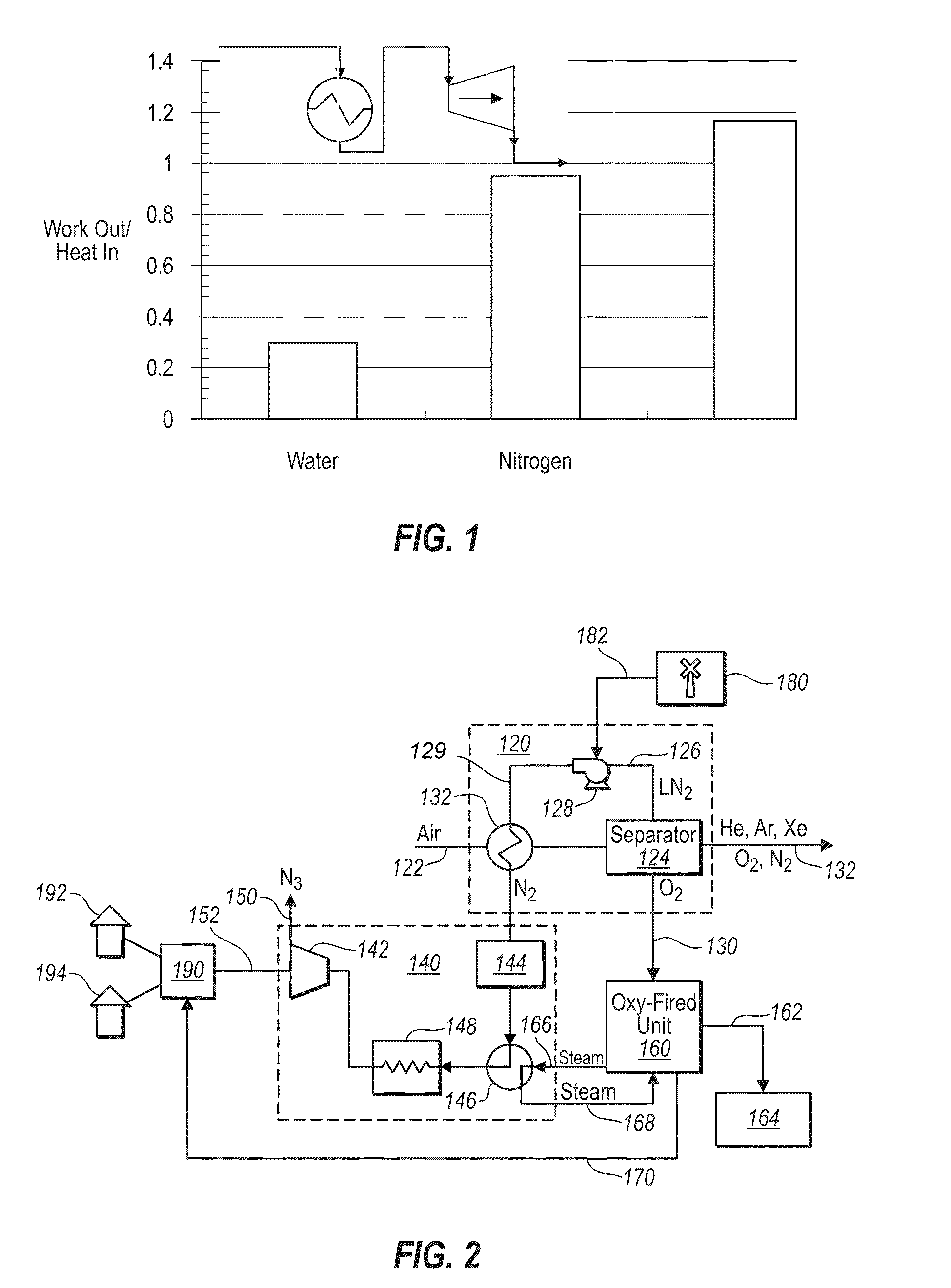
[0018]The present disclosure relates to the integration of an air separation unit with a power generating plant to improve the efficiency of power generation. The methods and systems improve efficiency of power generation by utilizing liquid nitrogen from the air separation unit as the working fluid in a turbine. Importantly, the liquid nitrogen is pressurized while in the liquid state. Pressurizing the nitrogen while in the liquid state provides significant improvements in efficiencies compared to compressing the gaseous nitrogen. While transporting and operating the nitrogen stream at pressure requires additional hardware specifications, the improved efficiencies have been found to be more than adequate to compensate for these added requirements.

[0019]Prior to expanding the compressed nitrogen in a turbine, the pressurized nitrogen stream can be used to cool the incoming air for the air separator unit. Once the pressurized nitrogen stream reaches ambient or near ambient, the press...


PUM


Abstract

An air separation unit is integrated with a power generating plant to improve the efficiency of power generation. The methods and systems improve the efficiency of power generation by utilizing liquid nitrogen from the air separation unit as the working fluid in a turbine. The liquid nitrogen is pressurized while in the liquid state. After warming the pressurized nitrogen stream by cooling the air for the air separator unit, the compressed nitrogen is expanded in a turbine to perform work. After expansion, the nitrogen is vented to ambient air. The nitrogen in its pressurized state can be used for energy storage and / or for smoothing out power demand on a power grid.

Description

THE FIELD OF THE INVENTION[0001]The present invention relates to methods and systems for generating power from a turbine using compressed nitrogen.THE RELEVANT TECHNOLOGY[0002]A significant portion of the world's electrical power is generated in power plants that burn fossil fuels. Electricity is produced by converting fossil fuels to thermal energy which is then used to drive a turbine. In a typical power plant, a fossil fuel is burned to heat water to create steam and the steam is used to drive the turbine. The turbine turns the generator to create electrical power that is distributed using a grid of power lines.[0003]The steam used in a modern power plant is typically recirculated in a closed loop system. Condensing and recirculating the water reduces the amount of water used to run the power plant. In addition, the recirculated water can be economically purified to prevent minerals and other components of common water supplies from damaging the power plant turbine and / or damagin...

Claims


Application Information

Patent Timeline
Patent Type & Authority Patents(United States)
IPC IPC(8): F01K25/06F01K13/00F01K25/10F22B37/00F23J15/06F23L7/00F25J3/04
CPCF01K25/10F23L7/007F01K13/00F22B37/008F23J15/06F25J3/04084F25J3/04533F25J3/04581F25J3/04612F25J3/04836Y02E20/322Y02E20/344Y02E20/346Y02E20/363F23J2215/10F23J2900/15061F23L2900/07001F25J2240/70F25J2260/30F25J2290/62Y02E20/30Y02E20/32Y02E20/34
Inventor BAXTER, LARRY L.
Owner U S BANK TRUST CO NAT ASSOC
Learn More