Method and apparatus for extended operation of steam turbines in islanding mode

Inactive Publication Date: 2015-02-24
BECHTEL POWER CORP
View PDF11 Cites 13 Cited by
  • Summary
  • Abstract
  • Description
  • Claims
  • Application Information

AI Technical Summary

Benefits of technology

[0014]A controllable clutch couples a shaft of the main steam turbine and a shaft of the rotating electrical machine during nominal operation of the power plant to generate alternating current to a power grid from torque applied by the main steam turbine to the rotating electrical machine. The industrial steam turbine, coupleable to the synchronous electrical machine at least during islanding mode, has a much smaller rating than the main steam turbine, for example 10% to 15% of a rating of the main steam turbine. Associated valves and controls are configured and controlled by the distributed control system of the plant to decouple the main steam turbine substantially from the source of pressurized steam during the islanding mode and to operate the industrial steam turbine for applying torque to the rotating electrical machine for supplying power equal to a house load of the plant.
[0015]At its small rating, the industrial steam turbine keeps the plant in a poised state ready for restarting. An auxiliary boiler can be provided to supply pressurized steam at a likewise small rating apt for operating the industrial steam turbine at a capacity for the which the auxiliary boiler and industrial steam turbine are optimized to operate together. In other respects, the nominal elements of the plant can be used at low ratings during islanding. The industrial steam turbine is coupleable to the main drive shaft to run the rotating electrical machine used as the electric generator for regular operation, but at lower power during the islanding mode. The industrial steam turbine exhausts to the plant main steam condenser to which the main steam turbine exhausts in the regular mode.
[0016]In some embodiments, the industrial steam turbine can be operated from other steam sources. For example, a steam exhaust path from the main steam turbine can be coupled to the industrial steam turbine. Alternatively, the industrial steam turbine can be powered from a steam bypass around the main steam turbine from the plant's primary steam generator if operated at a low level, for example in the case of a nuclear power plant where waste heat remains to be used or shed in the islanding mode.
[0017]Shifting between modes of operation is accomplished under control of a distributed control system coupled to associated valves and switches configured to operate the power plant in a power generation mode wherein torque from the main steam turbine is coupled through the clutch to turn the rotating electrical machine while operating as an electric generator for supplying electric power to the power grid. The distributed control system switches the power plant into an islanding mode wherein the main steam turbine is disengaged by the clutch and torque from the industrial steam turbine is coupled to turn the rotating electrical machine while operating as an electric generator for supplying electric power to operate the plant independently of power grid. The industrial steam turbine can be coupleable to and decoupleable from the rotating electrical machine by either a SSS clutch and gearbox or at least one of a torque converter and a gear transmission controllable by the distributed control s

Problems solved by technology

Among other reasons, the plant might be placed into islanding mode because the electric power transmission system that it normally supplies has gone down and is cold.
In such scenarios, the plant might be in islanding mode because of a planned occurrence or due to unplanned events.
In island mode while not connected to the grid, a power plant can be run at a very low output power level, for example producing only enough electric power to satisfy the “house load.” The plant is self-sufficient but not generating electric power to the grid.
Equipment issues can also result from other low load operational effects, such as erosion of last stage turbine blades due to spray cooling required at the turbine exhaust when operating

Method used


Image

  • Method and apparatus for extended operation of steam turbines in islanding mode
  • Method and apparatus for extended operation of steam turbines in islanding mode

Examples


Embodiment Construction

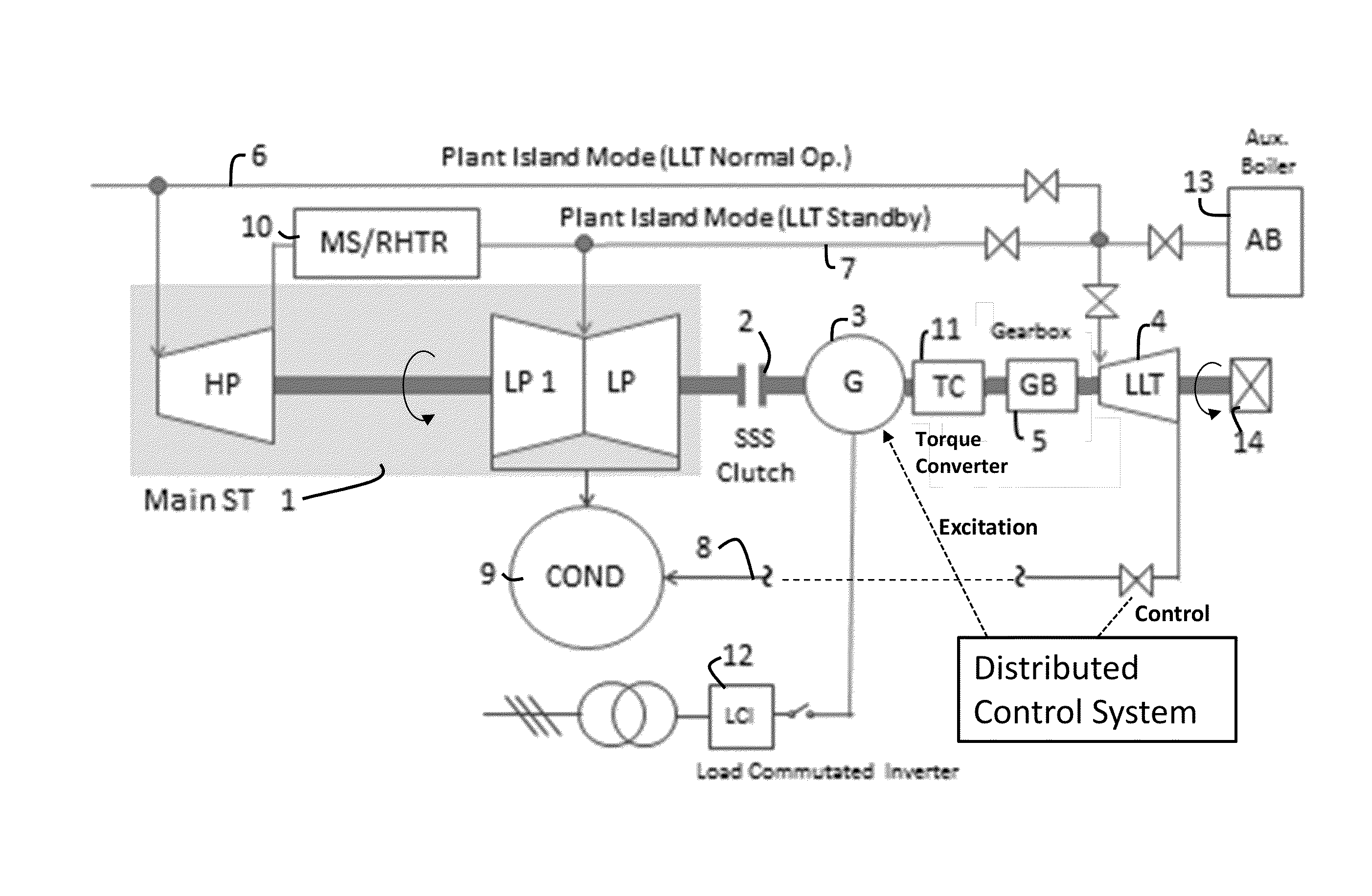
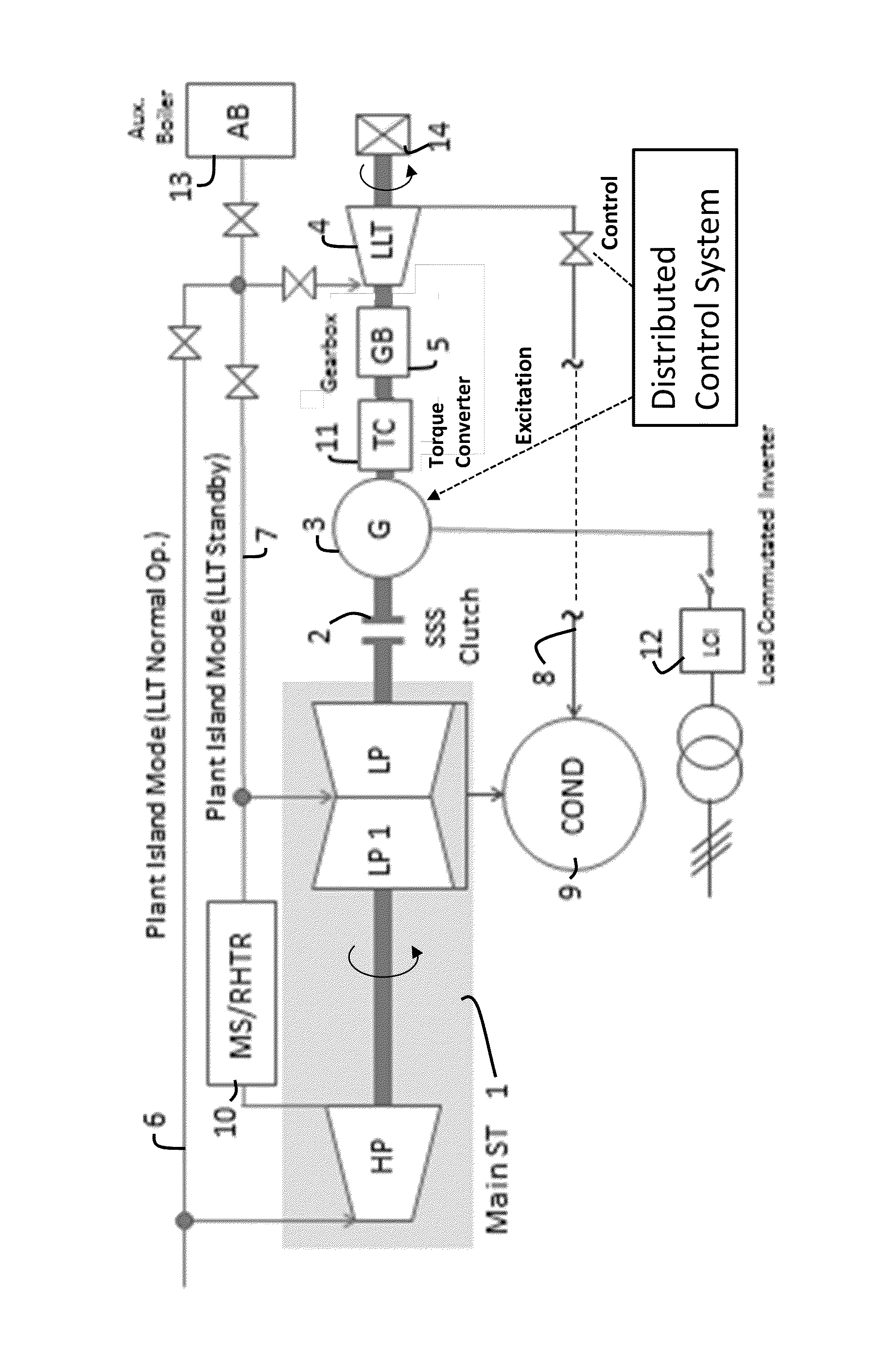
[0022]An inventive steam turbine powered electric power generation plant is shown schematically in FIG. 1. The FIGURE shows a large utility steam turbine 1 (herein the main ST or MST). The ST 1 can be of a type known for large fossil fuel fired boiler plants or nuclear power plants. As depicted in FIG. 1, the MST 1 can be considered, for example, a nuclear ST with separate HP (high pressure) and multi-flow low pressure (LP, LP1) sections separated by a combined moisture separator and reheater 10 (MS / RHTR). The MST 1 is connected to an electric generator 3 via a self synchronizing clutch, SSS 2.

[0023]Also connected to the electric generator 3 is a small steam turbine (herein the low load turbine or LLT 4). This turbine 4 can be similar in design to a boiler feed pump turbine (BFPT) of the kind sometimes deployed in large boiler plants. The LLT 4 is mechanically coupled to the electric generator 3 (rotating at 3,000 or 3,600 rpm). The term “coupled” as used herein defines an operation...


PUM


Abstract

A steam turbine driven electric power plant with an electric generator is switchable into an islanding mode wherein a main steam turbine is shut down and a lower capacity industrial steam turbine runs the electric generator instead, to supply house power to the plant while decoupled from the power grid. This avoids operating the main steam turbine and/or its steam source at reduced ratings for which they are not optimized and keeps the plant ready for restarting. The main steam turbine, the electric machine and the industrial steam turbine are mechanically engaged or disengaged through an SSS clutch, torque converter and transmission. In another mode, the electric generator is decoupled mechanically and operated as a mechanically unloaded synchronous motor coupled to the power grid, namely as a synchronous condenser wherein phased over- or under-excitation of the motor field windings supplies reactive power to the grid.

Description

FIELD OF THE INVENTION[0001]This invention concerns methods and configurations that facilitate running a steam turbine electric power generation plant in “islanding” mode, potentially for an extended period of time (several days). The invention is applicable, for example, to fossil fuel fired and nuclear powered plants.BACKGROUND OF THE INVENTION[0002]When in “island” or “islanding” mode, a steam turbine (ST) power plant is electrically isolated from the outside grid to which the plant normally supplies electric power (hence the name islanding). Among other reasons, the plant might be placed into islanding mode because the electric power transmission system that it normally supplies has gone down and is cold. Or the plant might be placed into a standby state while the power transmission system is operational and powered from other sources, e.g., for plant maintenance. In such scenarios, the plant might be in islanding mode because of a planned occurrence or due to unplanned events. ...

Claims


Application Information

Patent Timeline
IPC IPC(8): F01D15/10F01D13/02F01D17/10
CPCF01D15/10F01D13/02F01D17/10F01K7/08F02C9/18
Inventor BOULDEN, MARK S.GULEN, SEYFETTIN C.
Owner BECHTEL POWER CORP
Why Eureka
Try Eureka