Electronic safety device for a protection barrier

a technology of electronic safety device and protection barrier, which is applied in the direction of program control, frequency analysis, angle demodulation, etc., can solve the problems of introducing distortions that might significantly change the amplitude value, the circuit complexity required by the duplication of all control elements, and the signal is poorly immune, so as to achieve high efficiency and relatively cost-effective

Active Publication Date: 2015-03-10
PIZZATO ELETTRICA
View PDF5 Cites 0 Cited by
  • Summary
  • Abstract
  • Description
  • Claims
  • Application Information

AI Technical Summary

Benefits of technology

[0020]The object of the present invention is to overcome the above drawbacks, by providing an electronic safety device for protection barriers that is highly efficient and relatively cost-effective.
[0021]A particular object is to provide an electronic safety device for protection barriers that is difficult to tamper and ensures a high safety degree.
[0022]A further object of the present invention is to provide an electronic safety device for protection barriers that can assess the distance between the moving part and the stationary part in a particularly accurate manner.
[0024]A further object of the present invention is to provide an electronic safety device for protection barriers that uses a smaller number of components and requires relatively low manufacturing costs.
[0025]Yet another object of the present invention is to provide an electronic safety device for protection barriers that ensures high versatility and can use various types of RFID transponders.

Problems solved by technology

Nevertheless, these solutions also have drawbacks, as any interference might cause reading errors and resulting failures.
While this device provides a higher safety degree, due to the redundancy of the control circuits, it still suffers from certain drawbacks, one of which is the apparent circuit complexity required by the duplication of all the control elements.
Furthermore, the distance between the transponder and the reading head is assessed by detecting the amplitude of the received return signal, which may easily change due to spurious interferences in the area around the device.
Furthermore, the control circuit directly operates on the waveform of the received signal, and this might introduce distortions that might significantly change the amplitude value, particularly in case of malfunctioning.
A further drawback of this solution is that the received signal is poorly immune to background noise and such signal can be only properly detected by providing the control circuit with highly effective and relatively expensive filters, which must be further centered in a particularly accurate manner around the signal transmission frequency, with poor adaptability of the filtering features to the various types of commercially available transponders.
Furthermore, the provision of a device for monitoring the amplitude of the received signals and the checking elements further reduces the possibility of using various types of RFID transponders, with different transmission frequencies.
Finally, the device for monitoring the level of the received signal is connected downstream from the antenna of the reading head and may be affected by the temperature of the outside environment in which the electronic safety device is installed.

Method used


Image

  • Electronic safety device for a protection barrier
  • Electronic safety device for a protection barrier
  • Electronic safety device for a protection barrier

Examples


Embodiment Construction

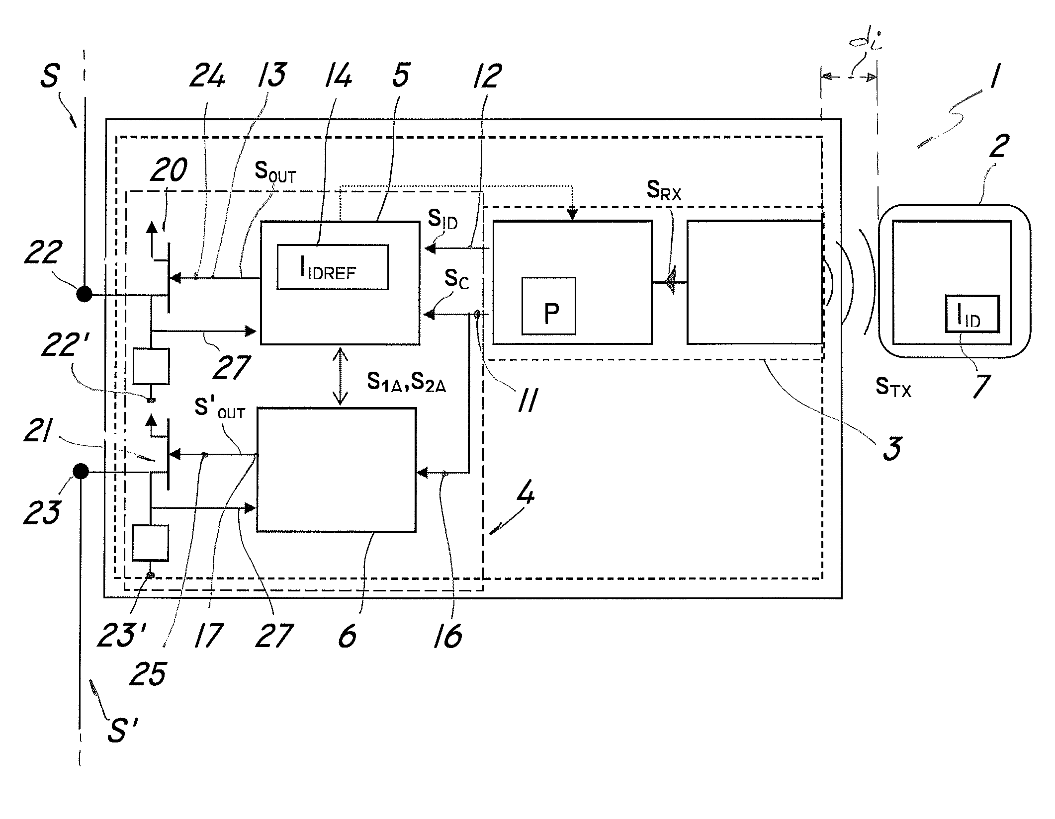
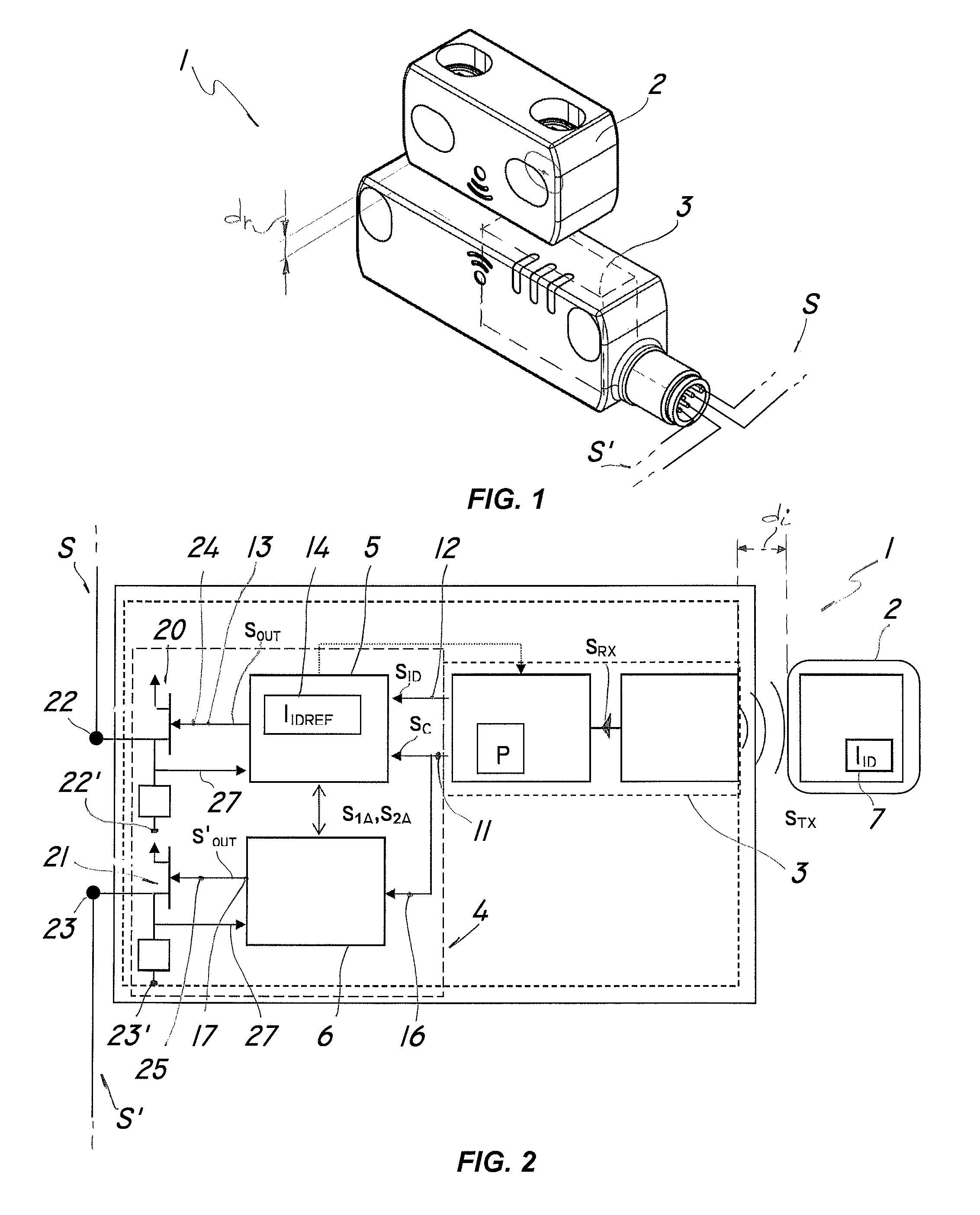
[0037]Referring to the above figures, an electronic safety device for a protection barrier, generally designated by numeral 1, may be mounted to a protection barrier or a working area, not shown and known per se, having one or more safety electric circuits S, S′.

[0038]Particularly, the barrier may include a fixed working area delimiting frame and a movable part, which is adapted to allow controlled access of an operator therein.

[0039]The device 1 may be electrically connected to one or more warning, emergency or alarm safety circuits S, S′ to trigger the latter at the same time as the moving part of the protection member is opened or closed, thereby ensuring the requested safety.

[0040]An electronic safety device 1 for a protection barrier of the invention comprises a transponder 2 that is designed to be anchored to the movable part of the barrier in which an identification code IID is stored.

[0041]Furthermore, the device comprises a transceiver device 3 designed to be anchored to th...


PUM


Abstract

An electronic safety device for a protection barrier includes a transponder, a transceiver device for receiving a return signal from the transponder, the transponder being movable with respect to the transceiver and adapted to be placed at a current distance, an electric circuit which is switched when the distance is lower or higher than a reference distance and a control and switching system. The transceiver device processes the return signal to generate a control signal with an electric parameter variable in function of the distance. The control signal is a periodic signal with a frequency and has a first spectrum with a middle interval and a second spectrum with lateral intervals shifted with respect the middle interval when the distance is higher than the reference distance, the parameter being associated to a frequency value that comprises either into the middle interval or into one of the lateral intervals.

Description

FIELD OF THE INVENTION[0001]The present invention generally finds application in the field of electric safety devices and particularly relates to an electronic safety device for a protection barrier.BACKGROUND ART[0002]A number of electronic safety devices are known, which are adapted for use with protection barriers for industrial plants, and are designed to open an electric circuit in case of emergency or hazard for a user.[0003]Particularly, such known devices comprise a first portion associated with a stationary part of the barrier and a second portion associated with a moving part of the barrier, e.g. a protection member, a door or the like, to monitor the opening and closing states thereof and stop the operation of the plant if the barrier is open.[0004]Namely, the device comprises one or more switches, which are designed to change their own electrical state from closed to open or vice versa, in function of the distance between the stationary portion and the moving portion.[00...

Claims


Application Information

Patent Timeline
Patent Type & Authority Patents(United States)
IPC IPC(8): G01R23/02H03K17/00H03K17/60H03K17/95
CPCH03K17/00H03K17/9502H03K17/60H03K2217/958
Inventor PIZZATO, GIUSEPPE
Owner PIZZATO ELETTRICA
Why Eureka
Try Eureka