
Highly directional thermal emitter

a thermal emitter and high-direction technology, applied in the field of thermal emission, can solve the problems of high confinement and high loss of conventional spp's, and achieve the effects of high reflectivity of solar radiation, increased bandwidth tailoring, and high degree of angular dependen

Active Publication Date: 2015-03-24
NAT TECH & ENG SOLUTIONS OF SANDIA LLC
View PDF3 Cites 13 Cited by
  • Summary
  • Abstract
  • Description
  • Claims
  • Application Information

AI Technical Summary

Benefits of technology

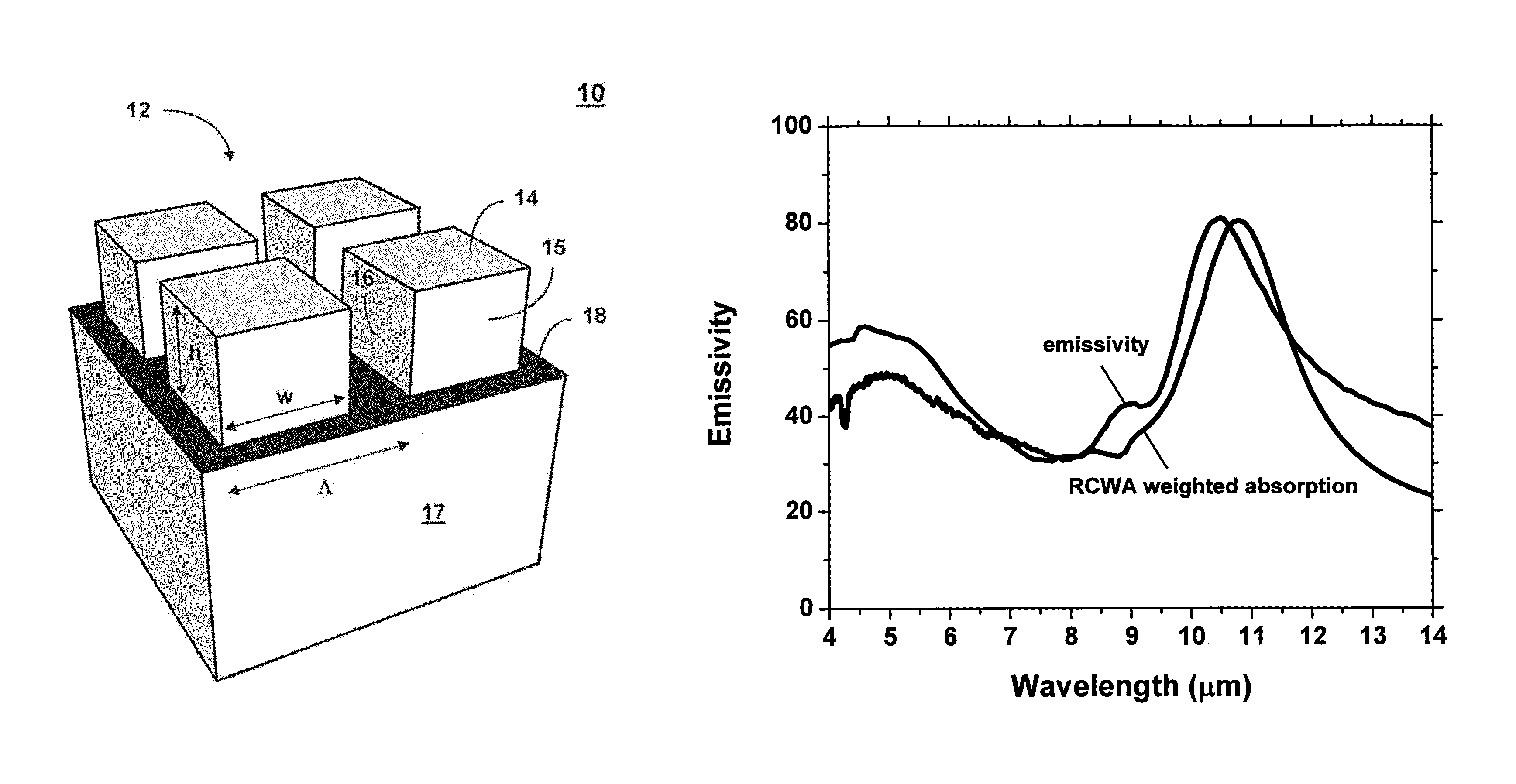
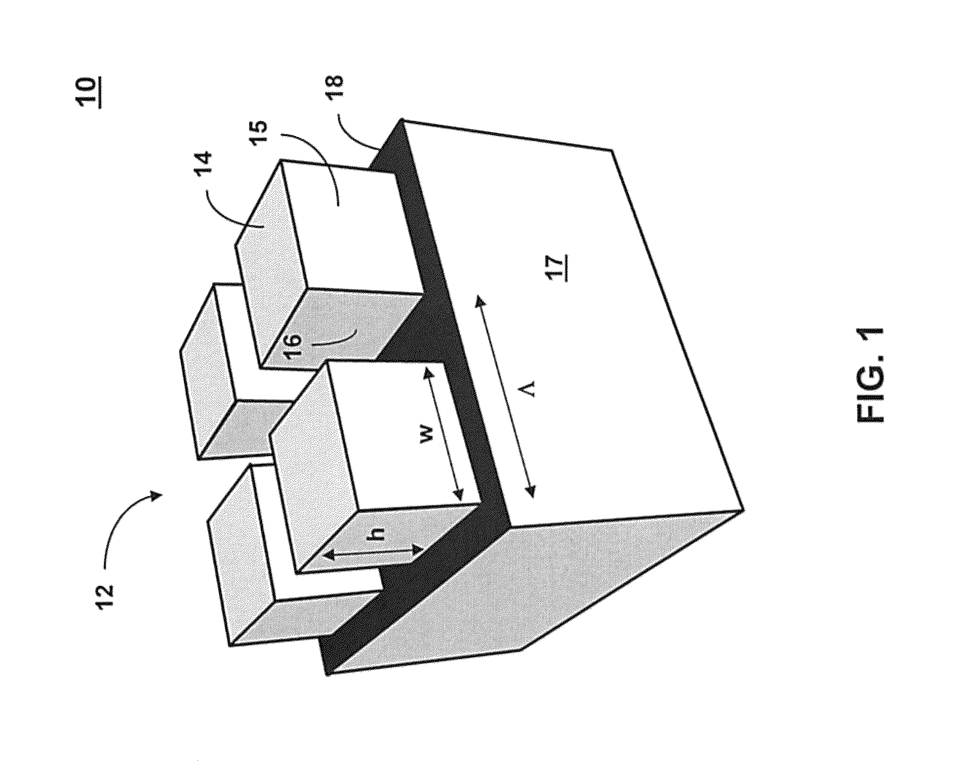
The invention is about a device that releases light in a very specific direction. It’s made up of tiny structures on a substrate that have a typical pattern. When the device is heated, it sends out light at a specific wavelength. The structures can be made from silicon or other materials, and they can be designed to be absorptive or reflective. The device can be used to control the direction of heat emission, making it useful in a variety of applications.

Problems solved by technology

These physical properties of the LWIR SPP's have made it a challenge to find efficient applications in this frequency range, though some have been demonstrated.
However, for further applications to be developed, a need remains for long-wavelength plasmons that can be generated with the high confinement and high loss of conventional SPP's.

Method used


Image

  • Highly directional thermal emitter
  • Highly directional thermal emitter
  • Highly directional thermal emitter

Examples


Embodiment Construction

[0017]The surface plasmon dispersion relation is given by:

[0018]ksp=k0⁢ɛm⁢ɛdɛm+ɛd,(1)

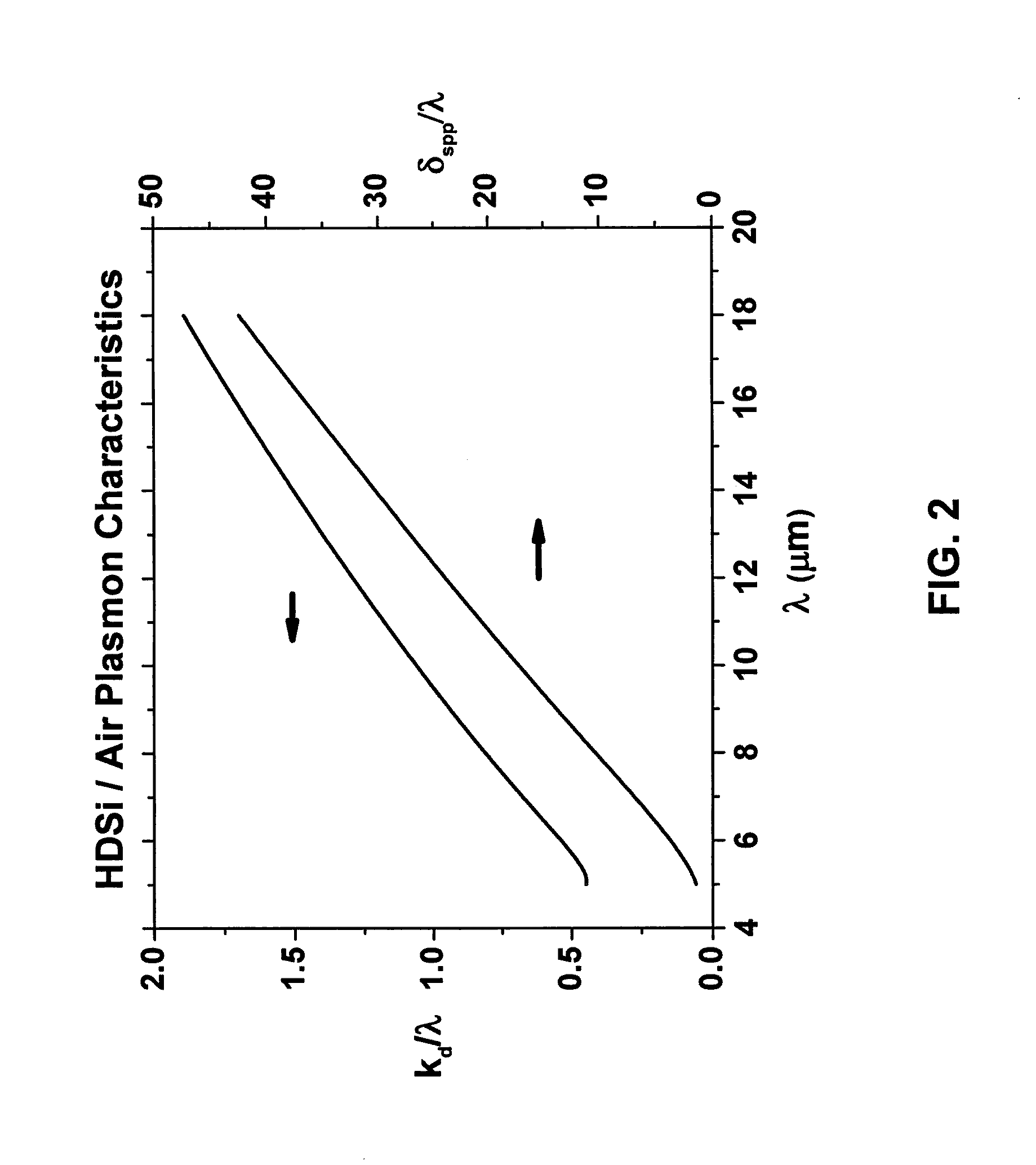
where k0 is the free space propagation vector and ∈m and ∈d are the complex metal and dielectric permittivities, respectively. All plasmon mode characteristics can be determined from this relation which is dependent on the relative magnitudes of ∈m and ∈d. The variation in the magnitudes of ∈m for the visible and infrared (IR) is the source of the physical distinctions and can be easily understood by using the Drude model to describe the optical dispersion of a medium with free electrons subject to collisional damping. Here, the frequency dependent permittivity is expressed as:

[0019]ɛ⁡(ω)=ɛ∞⁡(1+i⁢⁢ωp2⁢τω⁡(1-i⁢⁢ω⁢⁢τ)),(2)

where ∈∞ is the high frequency permittivity, ω is the exciting frequency, τ is the collision rate, and the plasma frequency:

[0020]ωp2=ne2m*⁢ɛ0⁢ɛ∞,(3)

is a function of the carrier density n, the effective mass m*, and ∈∞. In conventional metals, the plasma frequency is in the ultraviol...


PUM


Abstract

A highly directional thermal emitter device comprises a two-dimensional periodic array of heavily doped semiconductor structures on a surface of a substrate. The array provides a highly directional thermal emission at a peak wavelength between 3 and 15 microns when the array is heated. For example, highly doped silicon (HDSi) with a plasma frequency in the mid-wave infrared was used to fabricate nearly perfect absorbing two-dimensional gratings structures that function as highly directional thermal radiators. The absorption and emission characteristics of the HDSi devices possessed a high degree of angular dependence for infrared absorption in the 10-12 micron range, while maintaining high reflectivity of solar radiation (˜64%) at large incidence angles.

Description

STATEMENT OF GOVERNMENT INTEREST[0001]This invention was made with Government support under contract no. DE-AC04-94AL85000 awarded by the U.S. Department of Energy to Sandia Corporation. The Government has certain rights in the invention.FIELD OF THE INVENTION[0002]The present invention relates to thermal emission and, in particular, to a highly directional thermal emitter.BACKGROUND OF THE INVENTION[0003]Surface plasmons are coherent electron oscillations that exist at the interface between any two materials where the real part of the dielectric function changes sign across the interface (e.g., a metal-dielectric interface). When surface plasmons couple with an incident photon, the resulting hybridized excitation is called a surface plasmon polariton (SPP). Therefore SPPs are bound electromagnetic modes that can occur at metal-dielectric interfaces and correspond to polarization waves of free electrons in the metal. Therefore, electromagnetic modes can propagate along a bare metal ...

Claims


Application Information

Patent Timeline
Patent Type & Authority Patents(United States)
IPC IPC(8): H01L27/15G01J1/00H01L49/00H01L31/101H01L33/00H10N19/00H10N99/00
CPCH01L49/00H01L27/16H01L33/0004H01L31/101G02B1/002G02B5/008H10N99/00H10N19/00
Inventor RIBAUDO, TROYSHANER, ERIC A.DAVIDS, PAULPETERS, DAVID W.
Owner NAT TECH & ENG SOLUTIONS OF SANDIA LLC
Learn More