Solar receiver

a solar receiver and receiver technology, applied in the field of solar energy systems, can solve the problems of time-consuming alignment, limited performance of the above-mentioned “truss and glass” dish structure, and the need to re-do the alignment, so as to enhance the precision of the formed surface and enhance the effect of precision

Inactive Publication Date: 2015-04-14
SHELEF BEN +1
View PDF19 Cites 5 Cited by
  • Summary
  • Abstract
  • Description
  • Claims
  • Application Information

AI Technical Summary

Benefits of technology

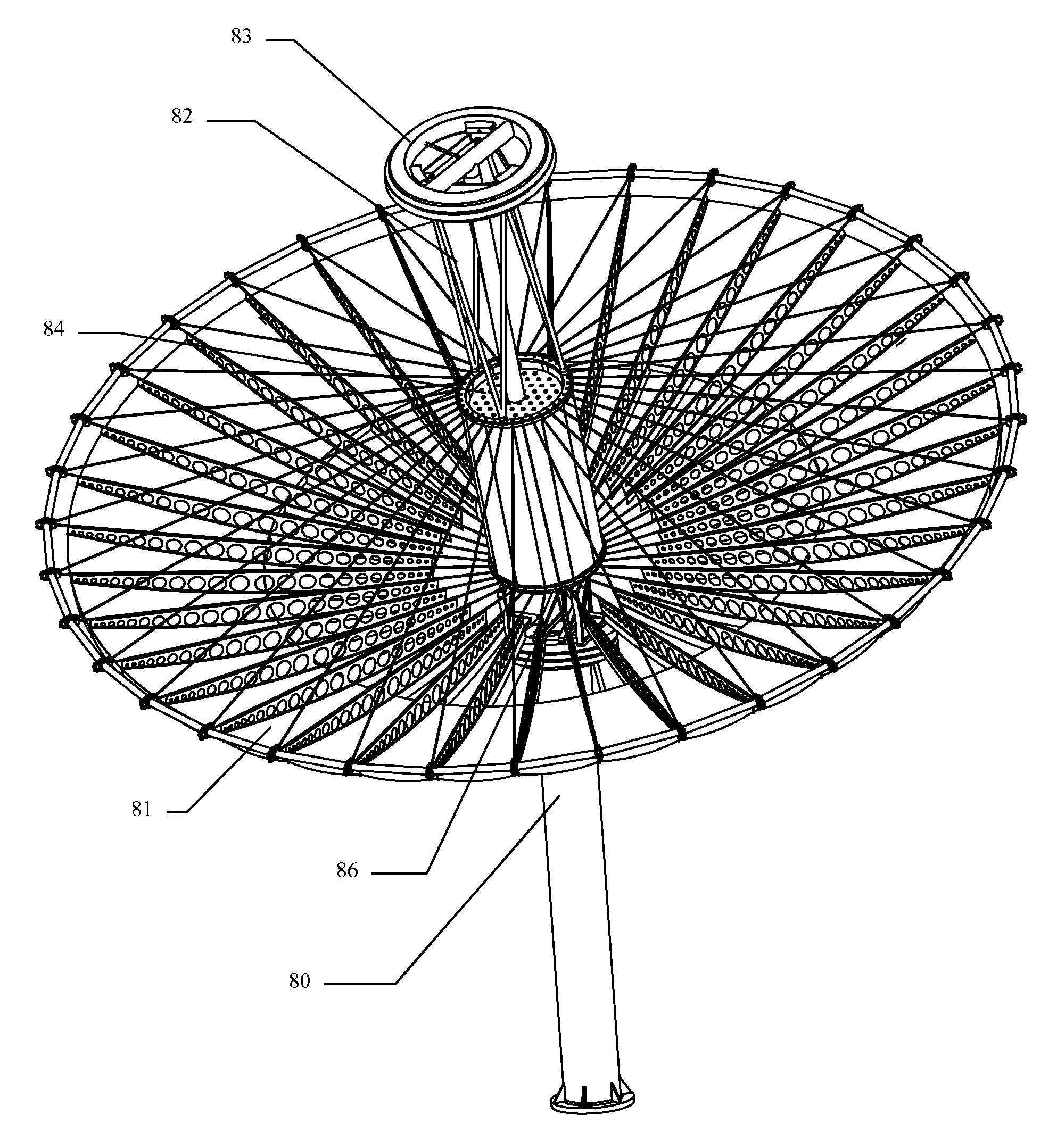
[0035]The primary reflector structure is based on a unique spoke-wheel-like tensile carrier structure that is very lightweight, has a low moment of inertia, high strength and stiffness, and allows for rapid field alignment during assembly. Reflector tiles are mounted to it to create the complete primary reflector.
[0048]The effect of a tracking error on the ringed receiver is always a predictable non-uniformity illumination pattern, with minimum and maximum illumination occurring on diametrically opposed points, along the direction of the tracking error (which is itself not known), and illumination varying smoothly between the minimum to maximum points. Taking advantage of this predictability, in order to reduce stringing losses, the cells are divided into several interleaved groups referred to as circuits, with each circuit having cells distributed essentially uniformly around the ring. Each circuit is wired internally in parallel so in and of itself can accommodate non-uniform illumination. However, since the interleaved circuits are affected in a similar way by this non-uniform illumination effect, the circuits can then be wired in series and only incur minimal stringing losses. The output from the individual cells of any of the circuits is also used as the sensor for providing feedback to the closed-loop tracking system.

Problems solved by technology

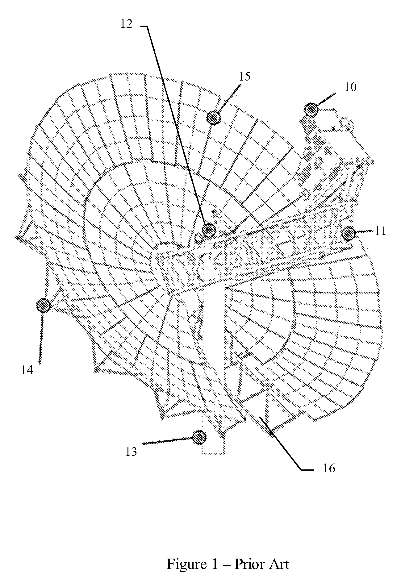
The “truss and glass” dish architecture described above is performance limited due to several factors.
Typical truss-based primary mirror designs weigh around 50 kg / m2, and their assembly and alignment in the field is very time consuming, taking more than a day for the 100 m2 reflector described above.
The large part count introduces tolerance stack-up errors, and the large number of joints are all sources of stress concentration, fatigue, and structural creep.
If the structure creeps over time, alignment has to be re-done.
The heavy weight of the dish and in particular its large moment of inertia makes precise tracking difficult, and either increases the cost of the actuation machinery or reduced tracking accuracy, which results in reduced output.
In boom-based designs, the mass is distributed in a dumbbell-like way, which is the worst case in terms of rotational moment of inertia, which makes tracking more difficult.
Boom flexing adds another oscillation mode and further complicates alignment and tracking.
The slice that has to be cut in the dish reduces the optical area, reduces its rigidity, and degrades optical accuracy.
The optical surface precision of the reflector tiles is also lacking in practice, due to the shell / glass structure having insufficient precision.
This problem can be solved with “brute force” precision optical processes such as glass grinding, but in solar power design, cost and fabrication speed are major design considerations, and those processes are prohibitive.
Finally, optical performance is hindered by accumulated dust and dirt on the optical surfaces.
Cleaning frequency is limited since it requires extensive manpower, and since it wastes large quantities of water.
Dense array photovoltaic receivers also suffer from several performance issues:
The receiver therefore has to reject the generated heat, and at 1000× illumination and with tightly packed PV cells this is a difficult problem, since there is very little area the cells can reject heat into.
Optical: Any lit area covered with the wires or traces used to collect the electricity from the front surface of the cells plus any gaps between the cells, do not produce electricity and thus lead to a corresponding loss in efficiency.
Electrical: The above constraints motivate the use of very thin conductors, which create Ohmic losses and wasted power in the conductor network.
The non-uniform illumination stems from several reasons, all ultimately stemming from the imaging nature of the paraboloid optics.
First, the sun is not a uniform source but rather a Gaussian one.
Finally, tracking errors move the sun away from the center of the image, so the point of peak illumination moves around and does not coincide with the center of the receiver, thus requiring the field of view of the receiver to extend around the nominal position of the sun and resulting in an image that is even darker in its periphery.
These effects create a large variance in the electricity production level of the cells, and so result in stringing losses.
The challenge in them is not simply to make electricity from solar light, but to do so in a way that has acceptable cost, construction time, efficiency, longevity, and environmental impact.

Method used


Image

  • Solar receiver
  • Solar receiver
  • Solar receiver

Examples


Embodiment Construction

System Level and Optical Path

[0092]FIG. 6 shows an embodiment of this invention using a solar thermal PCU. The system is comprised of a pedestal [60], pivot actuation machinery [66] at the top of the pedestal, a dish reflector [61], a hexapod mount [62], a thermal PCU [63] having a hot end [64], and a heat exchanger [65]. In this embodiment the hot end is shown surrounded by heat absorbing coils in which the thermodynamic fluid flows, but in other embodiments the heat can be transferred directly through the wall of the hot end.

[0093]Note that in this embodiment the thermal engine is oriented so that its hot end is away from the dish (opposite to the conventional mounting scheme), and the light illuminates its entire perimeter, transferring heat inwards. The structure of the dish is discussed further below under the sections “Alignable Carrier Structure” (ACS) and “Reflective Tiles”, and the placement and structure of the Thermal PCU is discussed under the section “Thermal PCU”

[0094]...


PUM


Abstract

A lightweight reflector with a load bearing structure based on a tensile spoke-wheel. The spoke structure is especially compatible with dish parabolic mirrors, but has utility as a carrier structure for any round functional surface, including flat or slightly-curved mirrors used in central tower solar systems, parabolic dishes for radio telescopes and antennas, and for non-concentrating thin film solar panels. There are no radial members loaded in compression. All the spokes pull the rim inwards, and the rim is compressed in the circumferential direction. The imbalance in spoke tension results from the application of load provides the rigidity of the rim in respect to the hub, both for in-plane and out-of-plane forces. Ribs stiffen the spokes to resist wind and gravity, but are not structurally supported by either the hub or the rim. Lightweight reflector tiles match the wheel structure and create the reflective surface.

Description

CROSS-REFERENCE TO RELATED APPLICATIONS[0001]This application claims priority from U.S. Provisional patent applications No. 61 / 323,857 filed on Apr. 13, 2010; No. 61 / 334,560 filed on May 13, 2010; No. 61 / 351,946 filed on Jun. 7, 2010; No. 61 / 370,755 filed on Aug. 4, 2010; No. 61 / 407,911 filed on Oct. 29, 2010; No. 61 / 432,584 filed on Jan. 14, 2011; the entireties of which are incorporated herein by reference.FIELD[0002]The present application belongs to the field of solar energy systems.BACKGROUND[0003]1. Context[0004]Concentrated solar power (CSP) systems are ones that concentrate incoming solar light before converting it into useful power. The conversion itself can be photovoltaic or thermal, but the common theme is that it is cheaper to collect the light over a large area and into a small power conversion unit (PCU) than it is to build a large power converter.[0005]There are several methods to concentrate solar power, including lenses, sun-tracking parabolic dish reflectors that ...

Claims


Application Information

Patent Timeline
Patent Type & Authority Patents(United States)
IPC IPC(8): H01L31/042F24J2/12F24J2/02F24J2/38F24J2/52F24S20/20F24S20/30F24S23/70F24S23/71F24S50/20H01L31/052
CPCF24J2/12F24J2/07F24J2/52H01L31/0525F24J2/523F24J2002/1085Y02E10/42Y02E10/47Y02E10/52Y02E10/41F24S20/20F24S23/71F24S25/00F24S25/10F24S40/20F24S2023/874H01L31/0547H02S20/10H02S40/425Y02E10/40
Inventor SHELEF, BENEREZ, SHMUEL
Owner SHELEF BEN
Why Eureka
Try Eureka