RFID reader

a technology of rfid reader and rfid antenna, which is applied in the direction of computer control, simulator control, indirect connection of subscriber, etc., can solve the problems of limiting the rate of data transfer and the need of the reader antenna to change state, so as to extend the read range of the system, reduce the power level, and enhance the effect of the percentage modulation of input power caused by the transponder

Active Publication Date: 2015-04-21
SUREFLAP
View PDF25 Cites 3 Cited by
  • Summary
  • Abstract
  • Description
  • Claims
  • Application Information

AI Technical Summary

Benefits of technology

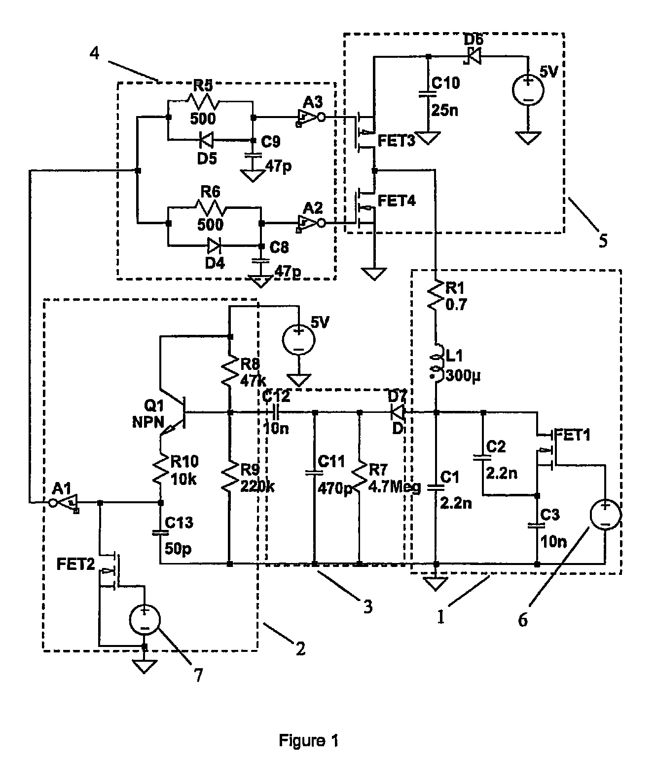
[0010]We describe an approach where negative feedback is introduced between the stimulus signal and the resonance amplitude. This feedback acts to keep the amplitude of the antenna voltage constant. Now load modulation by the transponder is quickly compensated for by a change in the reader to keep the antenna amplitude constant. In this manner the reader can adapt quickly to changes induced by the transponder, in embodiments avoiding the rate limitation associated with a high Q antenna. The modulation signal may be monitored indirectly through the change in the reader input into the resonance. Alternatively, if the feedback is less strong and the resonance amplitude is allowed to vary by some degree then the modulation may be monitored either through the reader input or through changes in the resonance amplitude. In this latter case the negative feedback still acts to reduce the amplitude variation and hence can increase the speed of response of the reader compared with a system without feedback.
[0013]The high Q of the reader antenna can be beneficial in extending the read range of the system. The high Q translates to a reduced level of power delivered to the antenna, for a given resonance amplitude. The percentage modulation in the input power caused by the transponder is therefore enhanced, making it easier to pick up at low levels. The use of a high Q reader antenna therefore has the potential to not only increase the efficiency of the reader but also extend the effective read range. Embodiments of the RFID system we describe may be incorporated in one or more of the following:

Problems solved by technology

Broadly these arise from the observation that the cause of the conventional bandwidth limitation is that the reader antenna is required to change state.
Any such change in state of a high Q system requires an increased timescale, limiting the rate of data transfer.
Consequently, when feedback is used to keep the amplitude of the reader antenna constant, this translates to a modulation of the power delivered to the antenna.

Method used


Image

  • RFID reader
  • RFID reader
  • RFID reader

Examples


first embodiment

[0048]The total energy supplied to the resonance is therefore a sensitive measure of the transponder modulation. FIG. 9 shows a schematic of the first embodiment with an additional section that measures current pulses though D6. A current measurement resistor R11 generates voltage spikes in response the diode current, which are capacitively coupled to ramp generator Q2. This generates a sawtooth waveform where the maximum voltage is mostly controlled by the duration of the current supply pulse. The maximum voltage is stored on C14 (less the Vbe drop of Q3), which also includes a decay resistor R16 such that this voltage may pickup both increasing and decreasing variations. Lastly Q4 provides gain and low pass filtering to reduce the amplitude of the ripple associated with the R16.

[0049]FIG. 10A shows the modulated transponder current and FIG. 10B shows the accompanying output voltage waveform, Vout. Vout provides an excellent measure of the modulation, especially exhibiting the diff...

fifth embodiment

[0071]FIG. 18 shows the invention. This embodiment comprises an antenna 16, reader 17, and lock 18 that is separably mounted on to a standard pet door 19. This has the advantage that the user does not need to replace a pet door that is already installed in their house, rather they may fix (retrofit) the external reader to the existing door. The external reader is mounted on the inside of the house and the lock prohibits the flap opening inwards when the desired pet is not registered; this prohibits unwanted animals from entering the house. The flap is free to open outwards, allowing exit to any animal in the house.

[0072]The antenna mounts onto or around the perimeter of the pet door or flap and the lock mounts at the base of the pet flap, either on the pet flap or on the door or wall in which the flap is provided. Any convenient mounting technique may be employed, for example, gluing, screwing or bolting. The lock is configured to be retrofitted to an existing pet door, in particula...


PUM


Abstract

Embodiments of the invention relate to the field of RFID (radio frequency identification). Some particularly preferred embodiments relate to a high-Q, so-called “full duplex” (FDX) RFID Reader. An RFID tag reader, the reader comprising: an electromagnetic (em) field generator for generating an electromagnetic (em) field for modulation by said tag, said modulation comprising modulated load of said em field by said tag; a detector system responsive to fluctuations in strength of said em field at said reader; a negative feedback system responsive to said detector system to provide a control signal for said em field generator for controlling said em field generator to reduce said detected fluctuations; and a demodulator responsive to said control of said em field to demodulate said em field modulation by said tag.

Description

FIELD OF THE INVENTION[0001]The invention broadly relates to the field of RFID (radio frequency identification). Some particularly preferred embodiments relate to a high-Q, so-called “full duplex” (FDX) RFID Reader.BACKGROUND OF THE INVENTION[0002]In an RFID system with a passive transponder generally the reader has two main functions. Firstly the reader supplies energy to the transponder through an RF energising field. The transponder picks this up with an antenna and resonant circuit tuned to the actuation frequency. Secondly, once the transponder is powered, the reader also needs to communicate with the remote device. These two tasks are quite different in nature and that can translate to conflicting requirements on the reader.[0003]The powering of the transponder is important in determining the read range of the system. The transponder and reader are often weakly coupled and care must be taken to maximise the energy transfer from reader to transponder. A resonant circuit is gene...

Claims


Application Information

Patent Timeline
Patent Type & Authority Patents(United States)
IPC IPC(8): G08B29/00G05B23/00G06F7/04G05B19/00G05B11/01G08B5/22H04Q5/22G08C19/16G01V15/00G06K7/00G06K19/07
CPCG01V15/00G06K7/0008G06K19/0723A01K11/006A01K15/021H03D1/02G07C9/28G06K7/10366E05F15/76E05F15/77
Inventor HILL, NICHOLAS PATRICK ROLAND
Owner SUREFLAP
Why Eureka
Try Eureka