High-power CW fiber-laser

a fiber-laser, high-power technology, applied in the direction of optical resonator shape and construction, semiconductor lasers, active medium materials, etc., can solve the problems of limited output power of fiber-lasers, reduced absorption efficiency, and reduced efficiency, and achieve the effect of minimizing the scattering of stimuli and high transmissivity

Inactive Publication Date: 2015-04-21
COHERENT INC
View PDF22 Cites 34 Cited by
  • Summary
  • Abstract
  • Description
  • Claims
  • Application Information

AI Technical Summary

Benefits of technology

[0015]In one aspect, laser apparatus in accordance with the present invention comprises a gain-fiber having first and second opposite ends and having a fundamental emission wavelength for laser radiation. The gain-fiber provides optical gain over a characteristic gain-bandwidth. A laser resonator is defined by the first end of the gain-fiber and a minor proximity-coupled to the second end of the gain-fiber. A first source of optical pump-radiation provides pump-radiation having a first pump-radiation wavelength. A second source of optical pump-radiation provides pump-radiation having a second pump-radiation wavelength different from the first pump-radiation wavelength. A dichroic beam combiner is provided for combining the first-wavelength and second-wavelength pump radiations. The mirror is highly reflective for wavelengths within the gain-bandwidth of the fiber, highly reflective for the first and second pump-radiation wavelengths, and highly transmissive for radiation having wavelengths longer than the gain-bandwidth. A focusing lens is configured to focus at least a substantial portion of combined first and second wavelength pump radiations into the first end of the gain-fiber, thereby causing laser-radiation at a natural wavelength within the gain-bandwidth to be generated in the laser-resonator, and delivered from the first end of the gain-fiber as output radiation. The gain-fiber is configured and arranged such that the generated and delivered radiation is multiple-lateral-mode radiation, and the transmission wavelengths of the mirror are selected such that collateral generation of stimulated Raman scattering is minimized.

Problems solved by technology

In theory at least, the output power of a fiber-laser is limited only by how much optical pumping power can be delivered into an optical gain-fiber for energizing a doped-core of the gain-fiber.
In practice, there are limits due, inter alia, to non-linear effects which can broaden the spectrum of pump radiation resulting in reduction of absorption efficiency, and photo-darkening of the fiber material which can lead to reduction of efficiency, excessive heating, and even catastrophic failure.
The non-linear effects become increasingly problematical as the gain-fiber is longer.
Fiber-splices and FBGs can be a source of instability due to transverse mode-coupling.
Other issues include grating walk-off and modal instability.
The latter issue arises because the fibre laser community, for the most part, is focussed on single-transverse-mode operation of the fiber-lasers in spite of the fibres themselves being multimode to avoid nonlinear impairments.
Any fiber-splice is potentially a source of loss, due to less-than-perfect core-alignment, and potentially a source of mechanical failure.
Clearly, the more splices the greater will be the potential for problems resulting from the aforementioned issues.
This radial asymmetry, however, makes focusing into a gain-fiber difficult and inefficient at best.

Method used


Image

  • High-power CW fiber-laser
  • High-power CW fiber-laser
  • High-power CW fiber-laser

Examples


Embodiment Construction

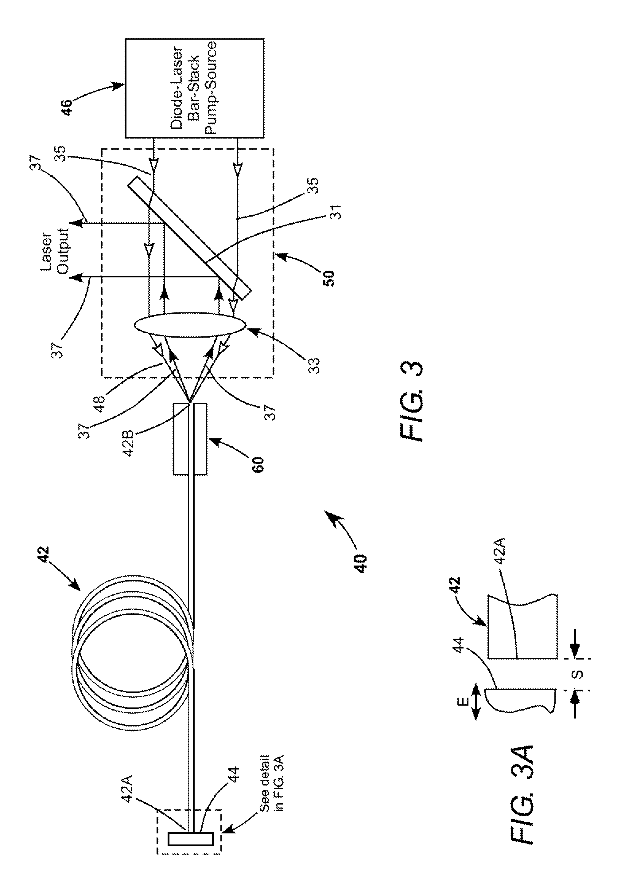
[0048]Continuing with reference to the drawings, wherein like components are designated by like reference numerals, FIG. 3 schematically illustrates a basic embodiment 40 of a fiber-laser in accordance with the present invention. Laser 40 includes a multi-mode gain-fiber 42 having a mirror 44 which is maximally reflective in the gain-bandwidth of the gain-fiber and proximity-coupled to one end 42A of the gain-fiber. The opposite end 42B of the gain-fiber is preferably left uncoated, which provides for only about 4% reflectivity, not significantly wavelength selective. This low reflectivity provides a very high (96%) output-coupling percentage for a resonator formed between mirror 44 and the uncoated end of the gain-fiber. In the inventive fiber-laser, output-coupling greater than 90% is preferred.

[0049]Pump-radiation for gain-fiber 42 is supplied by a diode-laser bar-stack source 46 including a plurality of diode-laser bars (not shown in FIG. 3). A combined collimated beam from the ...


PUM


Abstract

A CW ytterbium-doped fiber-laser includes a gain-fiber having a reflector proximity-coupled to one end, with the other end left uncoated. A laser resonator is defined by the reflector and the uncoated end of the gain-fiber. Pump-radiation from fast-axis diode-laser bar-stacks emitting at 915 nm and 976 nm is combined and focused into the uncoated end of the gain-fiber for energizing the fiber. Laser radiation resulting from the energizing is delivered from the uncoated end of the gain-fiber and separated from the pump-radiation by a dichroic mirror.

Description

PRIORITY CLAIM[0001]This application is a continuation in part of U.S. patent application Ser. No. 13 / 074,593, filed Mar. 29, 2011, which in turn claims priority to U.S. Provisional Application Ser. No. 61 / 451,335, filed Mar. 10, 2011, the disclosure of which is incorporated herein by reference.TECHNICAL FIELD OF THE INVENTION[0002]The present invention relates in general to fiber-lasers. The invention relates in particular to high-power, continuous wave (CW) fiber-lasers.DISCUSSION OF BACKGROUND ART[0003]Fiber-lasers are gradually replacing conventional solid-state lasers in several laser applications. Fiber-lasers have advantages over solid-state lasers in ruggedness and optical efficiency. CW fiber-lasers are capable of delivering a very high-powered beam, for example, a beam having a power in excess of 1 kilowatt (kW). Pulsed fiber-lasers can deliver peak-power as high as 10 kW or greater. Fiber-lasers can have a high optical efficiency, for example between about 60% and 90%.[00...

Claims


Application Information

Patent Timeline
Patent Type & Authority Patents(United States)
IPC IPC(8): H01S3/0941H01S3/00H01S3/04H01S3/042H01S3/067H01S3/08H01S3/094H01S3/105H01S3/106H01S3/16H01S3/17H01S5/00H01S5/40
CPCH01S3/06704H01S3/08059H01S3/09415H01S3/042H01S3/06733H01S3/0804H01S3/094015H01S3/105H01S3/1062H01S3/1618H01S5/4012H01S3/0407H01S3/173H01S2301/03H01S3/094011H01S3/09408H01S3/094096H01S5/005H01S3/005H01S3/0401
Inventor MINELLY, JOHN D.GOVORKOV, SERGEI V.SPINELLI, LUIS A.ANTHON, DOUGLAS WILLIAMINGALLS, JAY MICHAEL
Owner COHERENT INC
Why Eureka
Try Eureka