System for manufacturing an irrigation pipe and a device and method for detecting holes in the wall of an irrigation pipe

a manufacturing system and irrigation pipe technology, applied in the direction of drawing profiling tools, turning machine accessories, fluid tightness measurement, etc., can solve the problems of complex solution, high cost, and often revealed defects

Inactive Publication Date: 2015-05-05
MAILLEFER SA MAILLEFER SA
View PDF5 Cites 23 Cited by
  • Summary
  • Abstract
  • Description
  • Claims
  • Application Information

AI Technical Summary

Benefits of technology

[0017]The aim of the present invention is to provide a system for manufacturing an irrigation pipe and a device and method for detecting holes in the wall of this irrigation pipe more simple and less expensive than the known devices for detecting holes and without immersed electric devices.
[0030]The optical transmitter and receiver can have a parallel-pipe shape and comprise a cable face opposite to the emitting respectively receiving face of an optical signal. The cable face comprises the connection to a first respectively second cable, the emitting respectively receiving face comprise one or more opening, the number of which corresponds to the number of optical fibers—or signals—of the first and second cables. In fact, if there are N optical fibers in the cables—or if there is a single optical fiber comprising N wavelengths—the optical transmitter and receiver will comprise N openings on the emitting respectively receiving face, one for each optical fiber. In the case of the single optical fiber comprising N wavelengths, the optical transmitter acts as a WDM demultiplexer which splits the N wavelengths into different signals corresponding to different wavelengths; the optical receiver acts as WDM multiplexer which joins together these signals. In one embodiment, the optical transmitter and receiver comprise optical components, i.e. lens, mirrors, etc, for improving the transmission and / or the reception of the optical barrier if, for example, their distance is higher than some limiting value.
[0033]In one preferred embodiment the optical transmitter is placed facing the optical receiver, in order to optimize the light transmission. Advantageously the optical transmitter and receiver can comprise alignment and / or tilt screws for aligning and / or tilting the optical transmitter and receiver. An array of optical transmitters and receivers can be used to increase the length of the device and to make the gas bubble detection more effective.
[0040]The new solution has the advantage that it is considerably less expensive than the previous solutions and can be installed inside a cooling tank of any size.

Problems solved by technology

These defects often are revealed only after the irrigation pipes have been set in place on the ground.
This solution is complicated and requires expensive electric components like a camera and a numerical control device executing the processing algorithm.
The comparison of the pictures taken by the camera with the reference pictures cannot establish whether possible differences are caused by gas bubbles or some other effect.
Moreover, the described device is not adapted to the domain of the system for extrusion pipes manufacturing.
This solution is complicated and expensive since it requires a source of helium gas, a helium detector and an annular chamber.
The described system is not suitable for a continuous manufacturing process such as the extrusion of plastic pipes, wherein the irrigation pipe does not needed to be immersed in a liquid since it is already in the cooling liquid and it is not in a fixed position as the fuel tank of this document, but it is drawn by a traction unit.
The photocells and the light bulbs have to be powered by electric leads immersed in the water, creating a possible electrical hazard in the case of a non perfect water tightness.
Finally the system requires up to fifty photocells and light bulbs and is thus expensive.

Method used


Image

  • System for manufacturing an irrigation pipe and a device and method for detecting holes in the wall of an irrigation pipe
  • System for manufacturing an irrigation pipe and a device and method for detecting holes in the wall of an irrigation pipe
  • System for manufacturing an irrigation pipe and a device and method for detecting holes in the wall of an irrigation pipe

Examples


Embodiment Construction

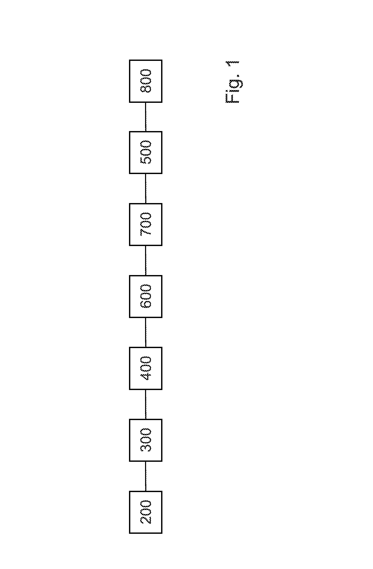
[0049]FIG. 1 shows an example of a system for manufacturing a drip irrigation pipe. It comprises an extrusion unit 300 (including the extrusion head) performing an extrusion process, a calibrator unit 400 for regulating the diameter of the irrigation pipe, a cooling unit 600 for cooling the pipe—comprising a liquid cooling tank which is some tens meters long and a cooling liquid, e.g. water, inside the tank—and a traction unit 500 for drawing the pipe through the liquid cooling tank. The speed of the irrigation pipe inside the liquid cooling tank is generally higher than 100 m / min, e.g. 120 m / min. The thickness of the walls of the produced irrigation pipe is in the order of magnitude of few tens of millimeters, e.g. 0.15 mm.

[0050]Drippers can be regularly fed into the extrusion unit 300 by a dripper insertion unit 200 comprising orientating means for feeding the drippers to the extrusion unit 300 in a determined orientation.

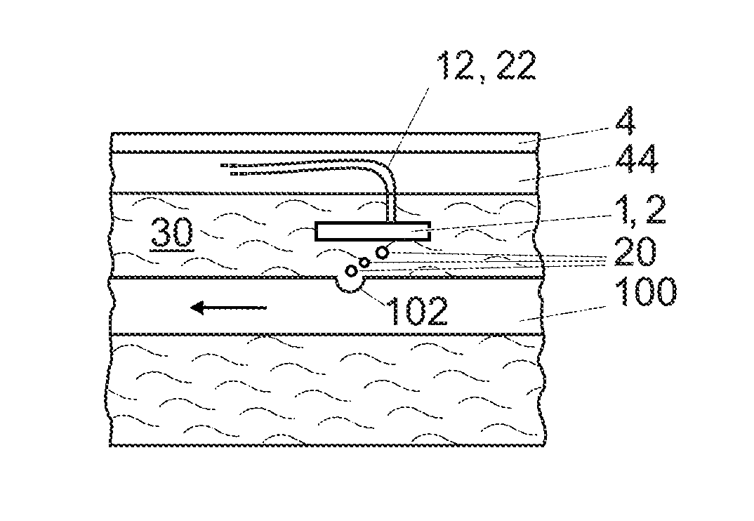
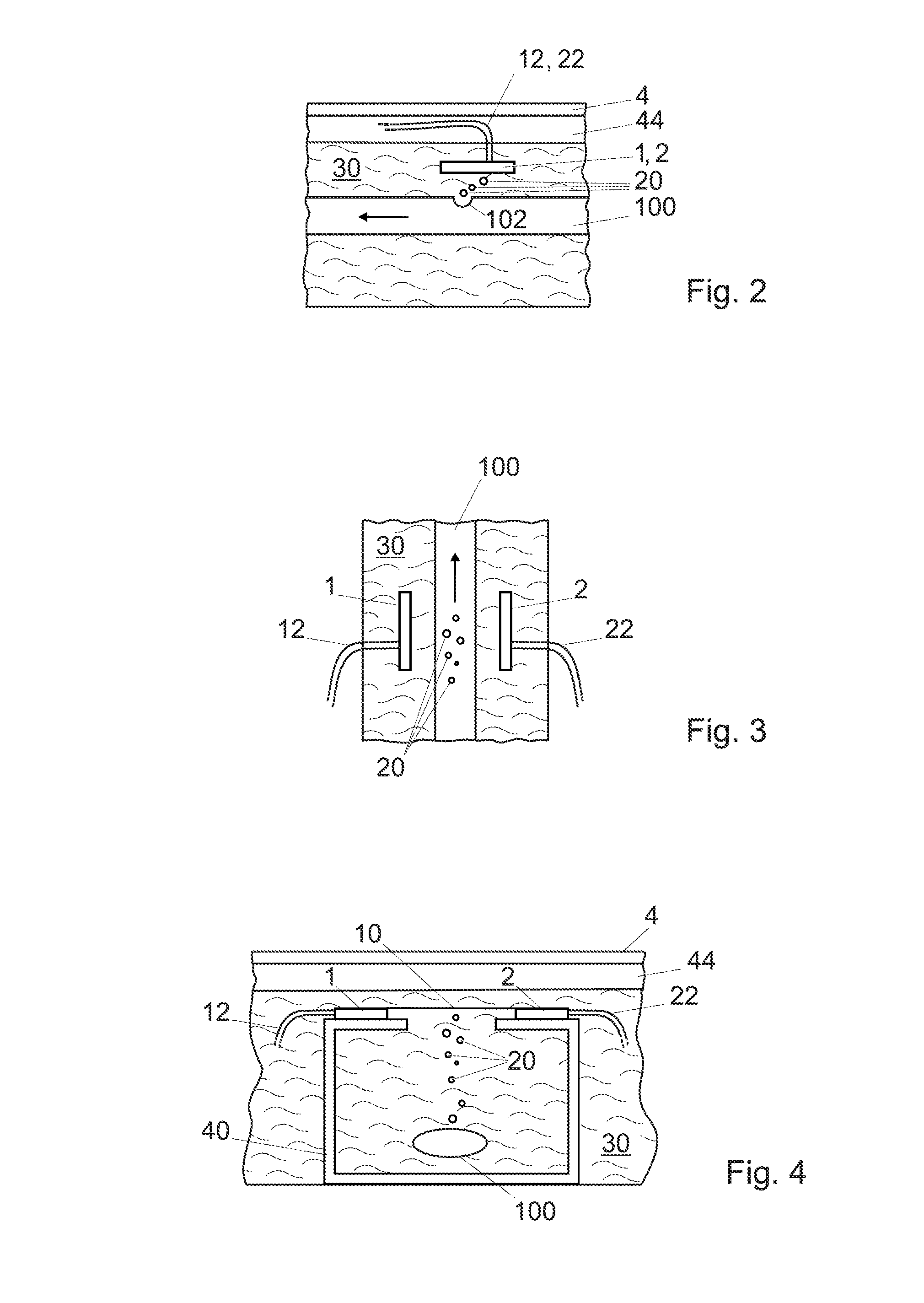
[0051]After the cooling tank 600, a perforating unit 700 ca...


PUM

PropertyMeasurementUnit
speedaaaaaaaaaa
speedaaaaaaaaaa
diameteraaaaaaaaaa

Abstract

A system for manufacturing an irrigation pipe comprises an extrusion unit, a calibrator unit, a cooling unit for cooling the irrigation pipe in a cooling liquid, and a traction unit for drawing the irrigation pipe in the cooling unit. The cooling unit comprises a device for detecting holes in the wall of the irrigation pipe and arranged for being immersed in the cooling liquid. The device for detecting holes comprises at least one optical transmitter and at least one optical receiver which define an optical barrier. The device is arranged so that the holes in the irrigation pipe located below the device produce gas bubbles which modify the optical barrier.

Description

FIELD OF THE INVENTION[0001]The present invention concerns a system for manufacturing an irrigation pipe, in particular a drip irrigation pipe, and a device and method for detecting holes in the wall of an irrigation pipe.DESCRIPTION OF PRIOR ART[0002]Some irrigation techniques use so-called “drip” irrigation pipes. The expression “drip irrigation pipe” indicates in this context an irrigation pipe, e.g. made of HDPE (High Density Polyethylene), pierced, at pre-determined intervals, by holes of small diameter, through which water can flow towards the ground. A dripper, which is a flow limiter, can be provided at each hole for precisely controlling the flow from the holes. It is generally made of plastic material and it is attached to the inner wall of the irrigation pipe during its manufacturing.[0003]Since irrigation pipes have a fixed cross-sectional profile, an extrusion process is generally used for their manufacturing. A device for manufacturing irrigation pipes generally compri...

Claims


Application Information

Patent Timeline
Patent Type & Authority Patents(United States)
IPC IPC(8): B29C47/20B29C47/90A01G25/02B21C31/00B29C48/09B29C48/32B29C48/90B29C48/92B29D23/00F16L55/00F17D5/00G01M3/08
CPCB21C31/00B29C47/8835B29C47/901B29D23/001G01M3/083A01G25/023B29C47/0023B29C47/903B29C47/92B29C2947/92228B29C2947/92285B29C2947/92295B29C2947/92723B29C2947/92942F17D5/00F16L55/00B29C48/919B29C48/905B29C48/09B29C48/92B29C48/901B29C48/903B29C48/913B29C2948/92228B29C2948/92285B29C2948/92295B29C2948/92723B29C2948/92942
Inventor WISLER, ALAINZARAMELLA, JEAN-CHARLES
Owner MAILLEFER SA MAILLEFER SA
Why Eureka
Try Eureka