Method for fabricating a high coercivity hard bias structure for magnetoresistive sensor

a magnetoresistive sensor and high coercivity technology, applied in the field of high coercivity hard bias structure for magnetoresistive sensors, can solve the problems of hysteresis or non-linear response of the sensor, degrade performance, and free layer becomes more volatile and difficult to bias, and achieves a high recording density and greater coercivity

Active Publication Date: 2015-05-19
HEADWAY TECH INC
View PDF14 Cites 3 Cited by
  • Summary
  • Abstract
  • Description
  • Claims
  • Application Information

AI Technical Summary

Benefits of technology

[0007]One objective of the present invention is to provide a hard bias layer with greater coercivity that enables magnetization stabilization in an adjacent free layer within a magnetoresistive sensor capable of high recording density.
[0008]A second objective of the present invention is to provide a method of increasing the coercivity in a hard bias layer without changing the elemental composition or thickness of the hard bias layer or underlying seed layer.
[0010]In one embodiment, smaller grain size in the hard bias layer is achieved by surface roughening the seed layer using a mild etching process that involves Ar ions or other inert gas ions. The mild etch may be performed in an ion beam deposition (IBD) chamber to remove about 5 to 10 Angstroms of seed layer and in so doing creates a higher density of nucleation sites. The nucleation sites have a higher surface energy than other regions of the seed layer surface thereby promoting a small grain size during subsequent deposition of the hard bias layer which may be formed in a single deposition step. It is observed by TEM cross-section analysis that the small grain size is about 30% to 40% less than achieved by conventional deposition methods.

Problems solved by technology

As the critical dimensions for sensor elements become smaller with higher recording density requirements, the free layer becomes more volatile and more difficult to bias which means the minimum longitudinal bias field necessary for free layer domain stabilization must be increased.
Imperfect alignment with a hard magnetic thin film such as a free layer can give rise to hysteresis or non-linear response of the sensor and thus noise.
Changing the thickness of the hard bias layer might require adjusting the thickness of one or more layers in the sensor which could degrade performance.

Method used


Image

  • Method for fabricating a high coercivity hard bias structure for magnetoresistive sensor
  • Method for fabricating a high coercivity hard bias structure for magnetoresistive sensor
  • Method for fabricating a high coercivity hard bias structure for magnetoresistive sensor

Examples


first embodiment

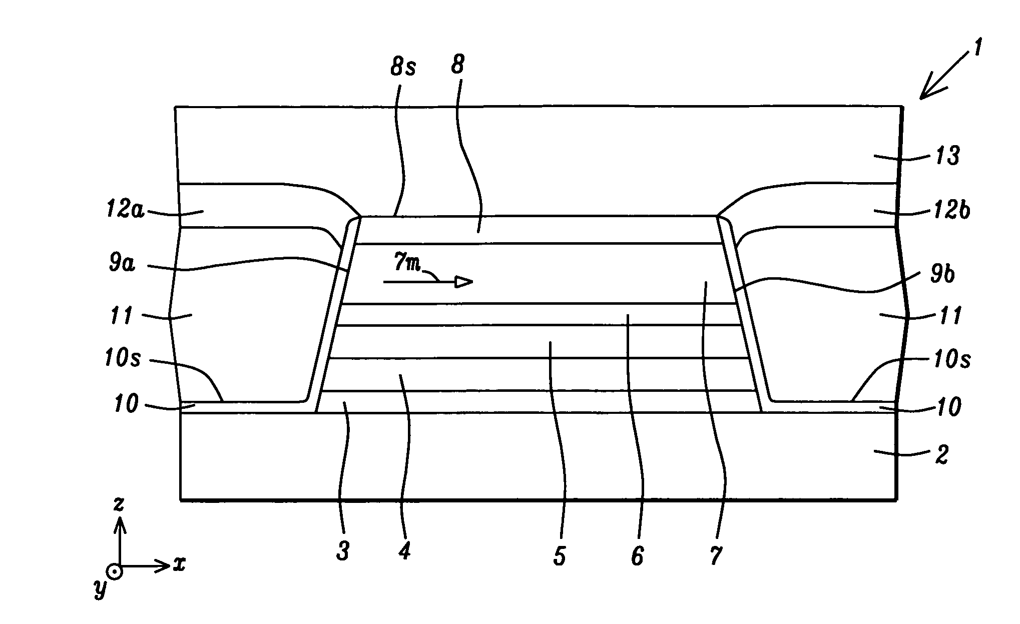
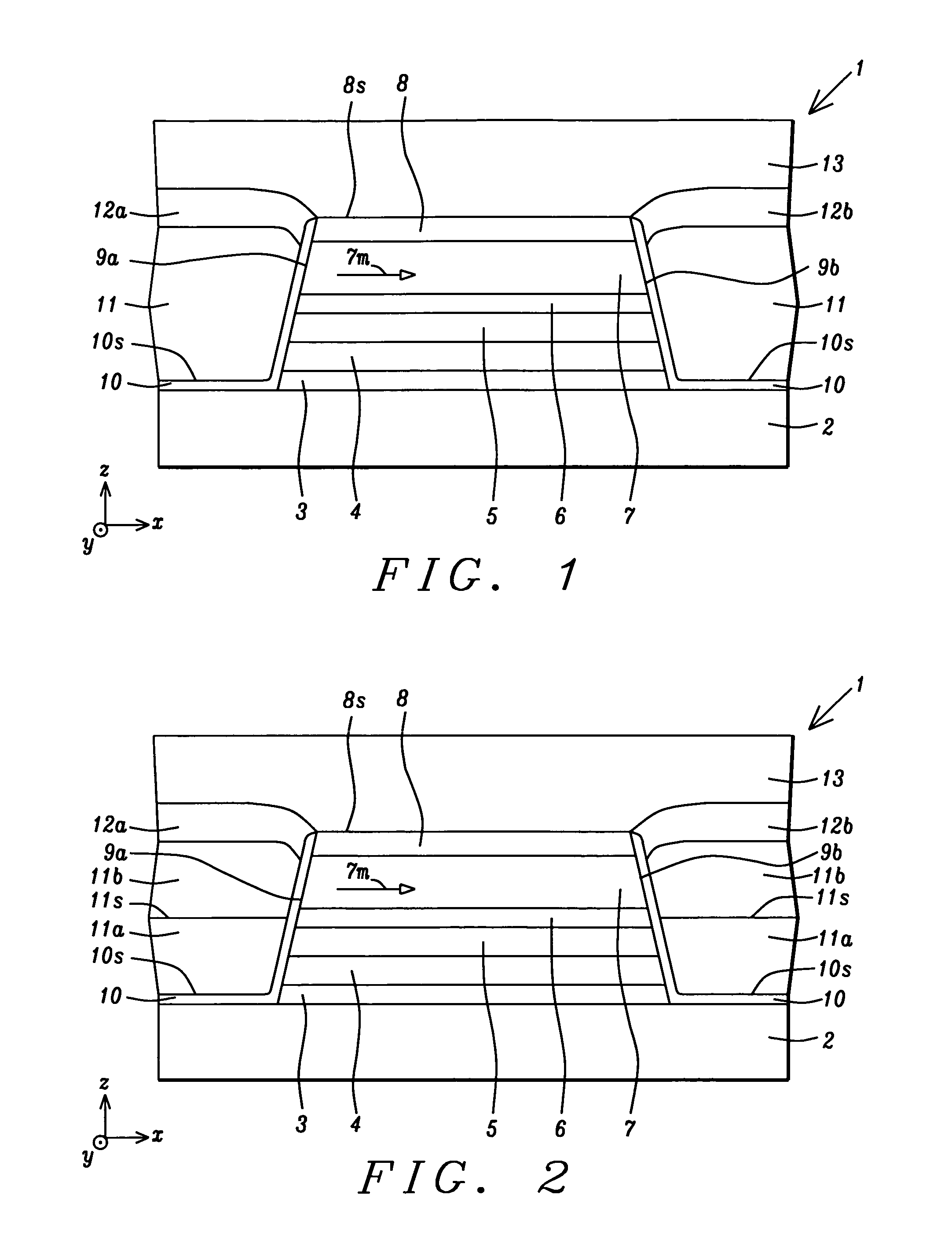
[0020]An important feature according to the present invention is a hard bias structure comprised of seed layer 10 and hard bias layer 11 formed on opposite sides of the sensor structure wherein the seed layer contacts the sensor sidewalls 9a, 9bincluding exposed portions of free layer 7. The hard bias structure described herein is designed to have a high coercivity in order to stabilize the magnetization of the free layer 7 along an easy axis which is depicted as the (+) or (−) x-axis direction. Preferably, the coercivity of the hard bias layer 11 is substantially greater than 2000 Oe, and more preferably, greater than or equal to about 2300 Oe in order to stabilize a free layer 7 in a sensor, especially in designs where a small sensor is required to meet requirements for a high areal recording density. For example, the hard bias structure prevents stray magnetic fields generated by a magnetic medium from inadvertently switching the magnetization direction of the free layer.

[0021]Th...

second embodiment

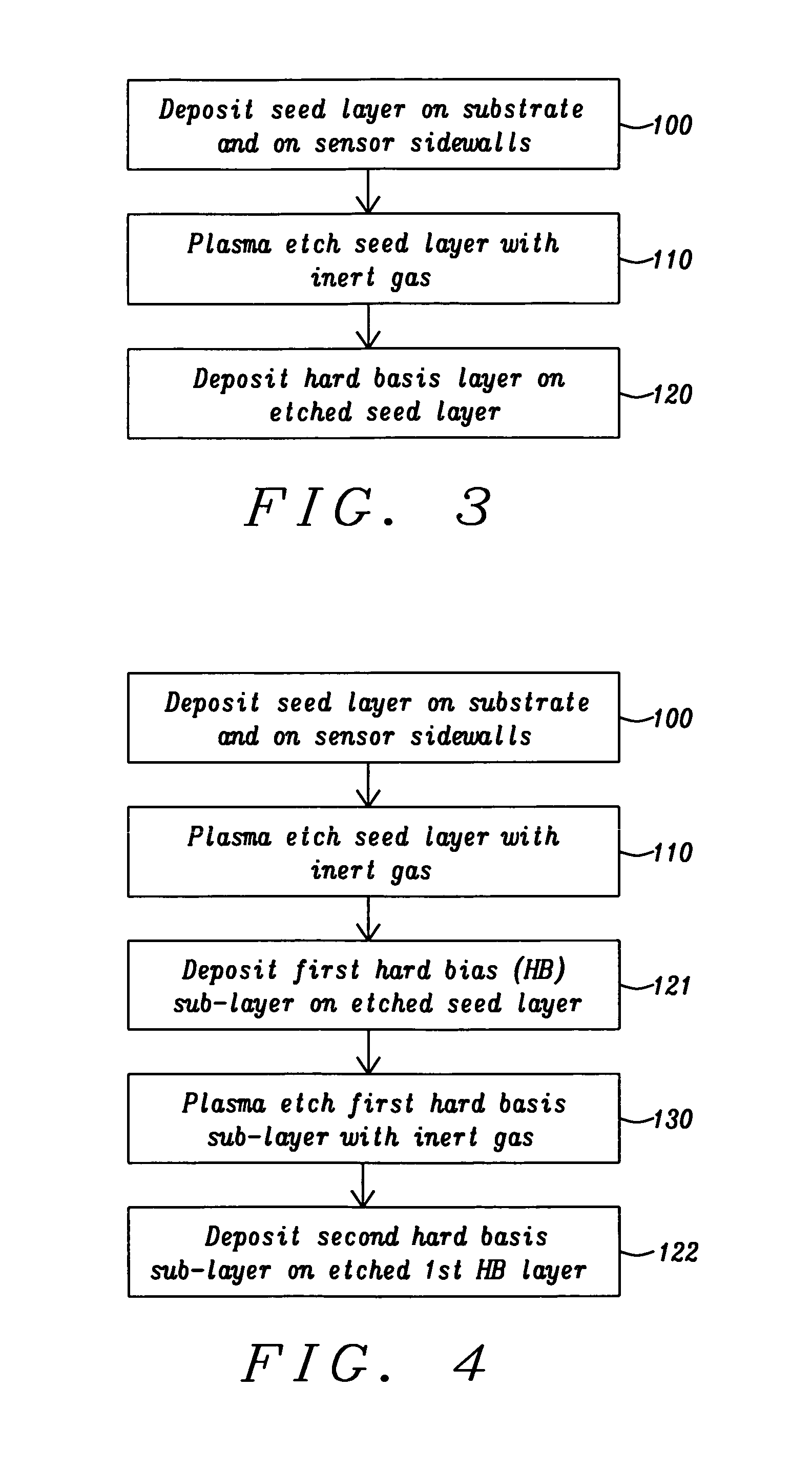
[0031]A process flow diagram for the second embodiment is illustrated in FIG. 4. Steps 100 and 110 are followed as in FIG. 2. Thereafter, in step 121, the first hard bias sub-layer is deposited by an IBD or sputter deposition process. In step 130, the first hard bias sub-layer is mildly etched by a process that may comprise the same conditions as described previously for the seed layer etch. In one aspect, a top portion about 10 to 15 Angstroms thick of the first hard bias sub-layer is removed during step 130 to provide a surface having an increased number of nucleation sites. During step 122, the second hard bias sub-layer is deposited on the etched first hard bias sub-layer. The increased number of nucleation sites on the surface of the etched first sub-layer is responsible for promoting a smaller average grain size in the second hard bias sub-layer formed in step 122, especially in a lower portion of the second sub-layer formed along the interface with the first hard bias sub-lay...


PUM

PropertyMeasurementUnit
thicknessaaaaaaaaaa
thicknessaaaaaaaaaa
thicknessaaaaaaaaaa

Abstract

A hard bias (HB) structure for longitudinally biasing a free layer in a MR sensor is disclosed that includes a mildly etched seed layer and a hard bias (HB) layer on the etched seed layer. The HB layer may contain one or more HB sub-layers stacked on a lower sub-layer which contacts the etched seed layer. Each HB sub-layer is mildly etched before depositing another HB sub-layer thereon. The etch may be performed in an IBD chamber and creates a higher concentration of nucleation sites on the etched surface thereby promoting a smaller HB average grain size than would be realized with no etch treatments. A smaller HB average grain size is responsible for increasing Hcr in a CoPt HB layer to as high as 2500 to 3000 Oe. Higher Hcr is achieved without changing the seed layer or HB material and without changing the thickness of the aforementioned layers.

Description

FIELD OF THE INVENTION[0001]The invention relates to a method for achieving a hard bias (HB) structure with high coercivity that is necessary to stabilize the magnetization in an adjacent free layer in thin film magneto-resistive (MR) sensors.BACKGROUND OF THE INVENTION[0002]In a magnetic recording device in which a read head is based on a spin valve magnetoresistance (SVMR) or a giant magnetoresistance (GMR) effect, there is a constant drive to increase recording density. One method of accomplishing this objective is to decrease the size of the sensor element in the read head that is suspended over a magnetic disk on an air bearing surface (ABS). The sensor is a critical component in which different magnetic states are detected by passing a sense current through the sensor and monitoring a resistance change. A GMR configuration includes two ferromagnetic layers which are separated by a non-magnetic conductive layer in the sensor stack. One of the ferromagnetic layers is a pinned la...

Claims


Application Information

Patent Timeline
Patent Type & Authority Patents(United States)
IPC IPC(8): C23C14/58C23C14/14C23C14/02G01R33/09G11B5/31G11B5/39
CPCG11B5/3932C23C14/5833C23C14/5873C23C14/14C23C14/025G01R33/098G11B5/3163
Inventor ZHENG, MINZHANG, KUNLIANGLI, MIN
Owner HEADWAY TECH INC
Why Eureka
Try Eureka